Drifter Programming here again for another post of VHDL! I had in mind to upload about Testbenches only, but I found out that I never really talked about Datatypes, Objects, Operations etc. more specifically! I should have put all that stuff here, but for some reason I forget or thought of talking about it later and it never happened so here we are doing it now (before it's too late)! We will actually need all that to make a Testbench anyway tho. So, let's get started now...
Datatypes in VHDL:
There are not so many of them and we already talked a little bit about them already from time to time, but we never got deep into them. There are 3 main Categories of Datatypes: Numbers, Characters and Strings. The numbers can be integers in any numeric system (0, 2017, 98E7) where the single bit in binary is called bit and reals in any numeric system (0.1, 1.2385, 8.76B). For Characters we use all the Latin Alphabet Letters or even Numbers ('A', 'G', '5'). The Strings can be of characters ("string example") or of numbers that are mostly in binary ("00100101") and are called bit_vectors. You can also define Booleans with true/false value, but we mostly stick to bits.
You might remember the ieee.std_logic_1164 package that adds a new Datatype called std_logic that is similar to an bit, but can have more values. Using also ieee.numeric_std we then can use any operation we like! So, the bit gets overridden and becomes std_logic and the bit_vector becomes std_logic_vector.
"Objects" in VHDL:
Using these Datatypes we can not only define the Inputs, Outputs of a Circuit, but also Signals, Variables and Constants. We already talked about Signals and Variables some time ago when they were needed, but for the sake of coverage I will talk about everything!
Signals:
To define signals we use the following syntax:
signal signal_name, ..., signal_name : data_type;
To assign a value to a signal we do:
signal_name <= value;
The Inputs/Outputs declared in the entity are also signals. Signals will actually be translated as Cables from the Compiler/Simulator!
Variables:
To define variables we use the following syntax:
variable variable_name, ..., variable_name : data_type;
To assign a value to a variable we do:
variable_name := value;
Variables can only be declared inside of a process and will not be translated into any hardware part in the Circuit.
Constants:
To define and assign a constant we use:
constant const_name : data_type := value;
We use constants to make our VHDL Code more readable!
So, to define a constant integer k with value 5 we do:
constant k: integer := 5;
Operations in VHDL:
The main datatypes of VHDL are integer, boolean, bit and bit_vector. Including the std_logic and numeric packages we then can also use signed and unsigned integer values!
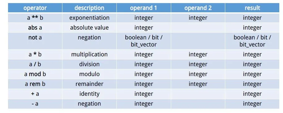
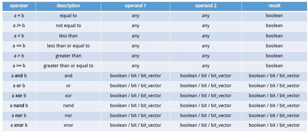
So, Standard VHDL includes the following Operations:

Using std_logic and numeric we get also those Operations:
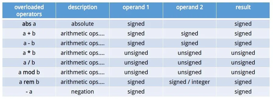
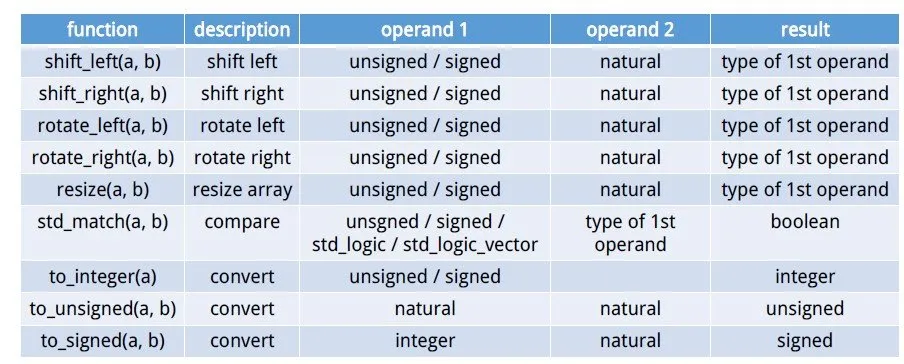
I found these tables in some Notes I had from University and I think that you can't get something better than that! You can see that there are plenty of them and all can have a purpose sometimes and help us out! It simply contains everything you will ever need for coding in VHDL.
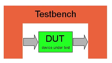
Testbench:
After all this stuff about Datatypes we can now jump into Testbenches! You will see that they are not so complicated. A Testbench doesn't describe a Circuit, but helps us simulate our Circuit checking specific Input Combinations out to see if we have any error or false outputs. So, a Testbench describes a way of assigning inputs to a Circuit.
Let's now get more specifically into the Coding Part. As you might already guessed a Testbench doesn't include a Entity! Inside of the Architecture we define a Component that is the Circuit that we want to simulate and test out! We also declare Signals with the same names as the Inputs and Outputs of our Circuit/Component. The Input ones will also be initialized mostly to some value. If we have a Sequential Circuit a Constant clock period will also be defined. After that we port map the component to the input/outputs signals we declared and then write 1 or 2 Processes. 1 Process will control the clock value if we have a sequential Circuit and the 2nd the other input values.
So, our Code Layout looks like this:
Entity tb isend tb;architecture arch of tb is-- declare component-- declare and initialize input signals-- declare output signals-- declare constant clockperiod if sequentialbegin-- port map component and signals-- process for clock switching if sequential-- process for input assignmentend arch;Example:
Let's get into a small example so that you understand it better!
I will use the NAND2 Gate in Behavioral that we used here.
The Code looks like this:
library ieee;use ieee.std_logic_1164.all;entity nand2 isport( a, b: in std_logic; c: out std_logic);end nand2;architecture arch of nand2 is begin process(a, b) begin if a='1' and b='1' then c <= '0'; else c <= '1'; end if; end process;end arch;Let's write a Testbench that checks all 4 different Input Combinations and run it in Modelsim!
library ieee;use ieee.std_logic_1164.all;entity nand2_tb isend nand2_tb;architecture arch of nand2_tb is component nand2 is port( a, b: in std_logic; c: out std_logic ); end component; signal a, b: std_logic:='0'; signal c: std_logic; begin nand2_gate: nand2 port map(a, b, c); process begin wait for 5 ns; b<='1'; wait for 5 ns; a<='1'; wait for 5 ns; b<='0'; wait; end process;end arch;
You can see that because the NAND2 Gate is not a Sequential Circuit we don't need to declare a clock period or process! We simply wait inside of the process for some nanoseconds so that the input combinations stay longer. I will not get into an Sequential Example, cause I have plenty of those for when we get into FSM's!
This is actually it for today! Hope you enjoyed it!
Until next time...Bye!