
Custom thumbnail using:
Introduction
Hello Steemians it's a me Drifter Programming!
Today we get back to Logic Design to talk about the implementation of ROM in the Hardware Description Language (HDL) that we covered during my series which is VHDL!
I highly suggest you to refresh your knowledge using my series that contains simulating the circuits and even the implementation of more complex units like the ALU that does mathematical operations for CPU's!
You can find the previous posts in my recap!
Also last time I implemented RAM which you might be interested in!
So, without further do, let's get started!
ROM architecture and types
To get into ROM we have to understand what it is.
ROM is Read-Only-Memory which means that predefined data/information (mostly) is written inside of it and we can only read this information and to do so we have to give an address, which corresponds to the point in the storage-array in which the needed data is stored. This makes ROM non-volatile memory cause it keeps the information stored "forever", unlike RAM which loses the information on a power loss or reset. So, ROM refers to memory that is hard-wired and cannot be changed after manufacture.
Modifying ROM data
Modifying the data stored inside of a ROM is very difficult, slow and sometimes not even possible. That's why such memory is mostly used to store firmware which doesn't need frequent updates. Firmware is software directly binded to the Hardware and mostly contains programs that need to be run at the system start (BIOS). But, restricting ROM from being altered in the manufacturing process makes it useless when an update is required to fix a security issue or bug that's been detected afterwards.
More recent ROM is read-only in normal operation, but can still be programmed using some other procedure. For example EPROM and EEPROM are 2 types of ROM which are erasable programmable read-only memories, where the second one is electrically erasable. This makes those types of ROM more useful, cause they can be erased and re-programmed, even if this process takes up a lot of time and needs special equipment.
Some info from wikipedia.
ROM I/O
So, what are the inputs of a ROM?
A ROM has the following inputs for sure which are:
- Data output -> information to read
- Address -> where the information is stored in the storage-array
- Enable or Read -> to signal that we want to read data
- Clock -> because ROM is a synchronous circuit (which of course also means that the requested data comes in the next clock period)
When having an erasable and re-programmable ROM then we also have:
- Data input -> information to store/write
- Re-write enable -> signal to request an erase and re-programming of the ROM's content
For "simple" and sometimes even more advanced circuits re-programmable ROM is not needed and so I will not implement it in VHDL. But, ROM in general is very useful in a lot of problems that we will discuss after implementing it in VHDL...
So, let's now get into the implementation part!
VHDL implementation of ROM by tweaking RAM
Having already code for a single-port RAM we can tweak it to get a ROM...
First of all some of the inputs are not needed anymore and so we delete:
- The mem_enable and rw_enable signals => we will now have a single rom_enable signal
- Data input => For our simple ROM no input is needed
We of course also don't need a signal anymore to store the address "temporary" when reading (cause reading is the only operation) and the process only has to check for a rising_edge of the clock and for the rom_enable signal to send the correct information to the output!
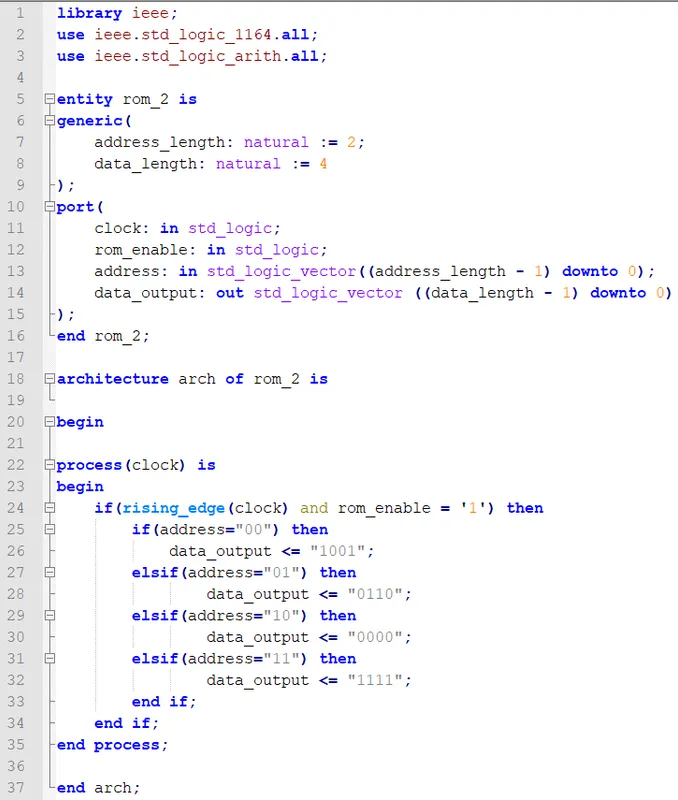
That way the code looks like this:

Note that I define the ROM entity in a "generic way", but to specify the actual constant data that is stored inside of the ROM storage-array we have to know the address and data-length to be able to write. For example in this code I have 2^2 = 4 elements which have a data-length of 4 bits...
When simulating in Modelsim we of course want the value "1001", "0110", "0000" and "1111" to appear in the clock after we set the address to "00", "01", "10" or "11" respectively!
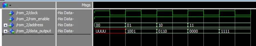
Here the simulation in Modelsim:

You can see that the requested data gets written to the output in the next rising_edge of the clock and so all this procedure took 5 clock-periods even if we only wanted to request 4 data!
VHDL implementation of ROM similar to a multiplexer
To refresh your knowledge let's quickly talk about what a multiplexer does...
A multiplexer (MUX) is a logical circuit that:
- has a specific number of inputs,
- a select signal that chooses which of the inputs should be passed to the output AND
- an output
You can clearly see that this is similar to the "addressing" that we did for ROM, which of course means that ROM can be implemented using the principle of a MUX!
This means that the address will act like a select signal and that we will have "predefined" inputs to choose from depending on the address that we take in as an input. Because ROM is synchronous we of course will have to put all this "procedure" below the check for a rising_edge of the clock and we also have to check if the ROM is enabled (rom_enable)!
So, the code looks like this:
You can see that I stored the same data in this ROM like in the previous one!
Of course here the "if else statement" is again dependent of the address and data-length, which means that hard-coding this information is again very time-consuming!
Let's simulate this circuit in Modelsim again:
As expected the ROM works just fine and might even be easier to understand for some people, cause it doesn't need type definition, integer conversions etc. which might be confusing for newcomers!
You can download the codes in the following links at pastebin:
How and when to use ROM in your designs
Like RAM, ROM should be used whenever you want to store a loooot of information! Of course ROM is a little bit special cause it can't be re-written afterwards (except if you implement like that), but when having something which is constant all the times then storing it constantly in a ROM might be very helpful and much easier to use!
So, use ROM wisely and only when it's really needed, cause as already told in the beginning of this post, it's very very difficult to make changes to it afterwards and by making ROM re-programmable you actually end up with special RAM which of course takes up a lot more space in the final circuit then an actual read-only memory!
And this is actually it and I hope that you enjoyed it!
Next time I think of starting with Verilog and after that we might start implementing the "more advanced" circuit that I promised :)
Bye!