
Image source: https://circuitglobe.com/difference-between-alternating-current-ac-and-direct-current-dc.html
Introduction
Hello it'a me again @drifter1! I'm back from vacation..as you can see..and so back into regular science articles. The articles about my vacation in Lemnos are very interesting and worth taking a look at, and I think that I gave you that vacation mood with such amazing pictures and descriptions of my Day's there! Today's article is the next article from the Electromagnetism series, where we will now start getting into Alternating current (AC)! Knowing stuff about "regular" Direct current (DC) that we covered till now, might be helpful. I will try to combine the new knowledge with the older one, by showing/analyzing the main and most important differences between the two. So without further do, let's get into it!
Phasor diagrams
Let's start out with Sinusoidal waveforms and the so called Phasor diagrams...
The diagram of a sinus or cosinus function is periodical and builds a waveform. These two functions (sinφ and cosφ) plot similar and have a Phase Difference of 90 degrees or π/2 rads as you can see in the following picture:

Image source: https://www.electronics-tutorials.ws/accircuits/phase-difference.html
Such waveforms can be represented mathematically as:

where:
- At is the value at a specific time t (in seconds)
- Amax is the maximum value that quantity A can reach (sin gives values in the range [-1...1])
- ω is the angular velocity that shows us how "fast" the waveform "flows" in time
- φ is the phase difference in comparison to the regular sinus-function
Such Sinusoidal waveforms can be:
- "In-phase", which means that both rotate at the same speed (ω) or frequency and reach the maximum negative and positive quantity values at the same instant of time
- "Out-of-phase", which means that they don't reach the maximum peak and zero values for the quantity at the same instant of time
Two terms that are used for the second "Phase relationship" are:
- Lagging Phase Difference -> a "negative" of angle -φ
- Leading Phase Difference -> a "positive" of angle φ
A vector that's rotating with ω rads/s from 0 up to 2π rad (or 360 degrees), following a complete cycle or completing one complete revolution of 2π, can be used to understand the Phase differences even better! Let's consider that a vector A of constant length is rotating around the center of the axes. The y-axis is representing the value of a physical quantity. At first (t = 0) this vector is parallel to the x-axis at 0 degrees angle. This vector rotates anti-clockwise with a speed of ω rads/s and so the angle at each moment is ωt. At 0, 180 (π), 360 (2π), ... degrees the vector is parallel to the horizontal axis x and so the value of the quantity is of course zero. At 90 (π/2), 270 (3π/2), ... degrees the value of the quantity reaches maximum peak level (positive and negative of course). After completing a full cycle the "numbers" repeat themselves and so what needs to be analyzed is only one complete, full cycle/revolution!
To understand this even better, here's a diagram:
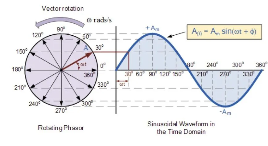
Image source: https://www.electronics-tutorials.ws/accircuits/phasors.html
On the left you can see that Rotating Phasor/Vector that I talked about. On the right you can see the plotting of the y-axis which gives us the value of physical quantity A in the so called Time Domain. You can clearly see how this vector follows the sinusoidal waveform that we covered previously!
To get back into Phase Difference think about the previous phasor again. If we start with the vector at 30 degrees angle instead of 0 at initial time t = 0 the diagram on the right would of course move to the left, which means that the quantity would have a non-zero value at t = 0. The quantity would also reach the maximum peak much faster then before. If we start at 90 degrees the value of the quantity would be the positive maximum and the sinus waveform would turn into a cosinus waveform! The maximum value that this quantity can reach is called "Magnitude" and is of course equal to the length of the Phasor.
Alternating current
Alternating current follows the periodical behaviour of such Phasors and Sinusoidal waveforms. Alternating current/voltage/charge periodically reverses, which means that it can start at zero, grow to maximum, decrease to zero, reverse until it reaches the maximum opposite direction, returns back to the original/initial value, and repeats this cycle indefinitely. Phase difference again plays a big role as the alternating current/voltage can also start at a non-zero value! The time interval between two successive cycles is called period. The number of cycles or periods per second is the so called frequency. We mostly talk about frequencies that start at 50 cycles per second (Hz) and can even reach millions or billions of them with mega- or even gigahertz.
Alternating current is invented by the famous scientist "Nicholas Tesla".
As you might remember from previous articles, angular velocity can also be described in terms of frequency or even period as:

where:
- ω -> angular velocity
- f ->frequency
- T -> period
Replacing ω in the waveform "equation" of before, we can write the mathematical formula of Sinusoidal waveforms again as:

where:
- A is the magnitude (maximum value) of the signal/current
- t is the current time
- f is the frequency of the signal/current
To produce such current we use the so called Alternators. The simplest method of generating AC current is using a "Basic Single Coil AC Generator" that is based on Faraday's Electromagnetic induction principle that converts mechanical energy into electrical energy. Such a generator consists of two permanent magnets that produce a fixed magnetic field between north & south poles. Inside of this field we place a single rectangular loop of wire. We rotate the loop of wire around a fixed axis that is perpendicular to the magnetic field generated by the two poles, directly cutting the magnetic flux produced. The change in magnetic flux (Len'z law) induces a current inside of the wire that opposes the change in magnetic flux. Because of the way that it rotates such current follows the Sinusoidal wave form that we talked about previously. This waveform of course has an amplitude and time period / frequency. Every complete cycle of this sine AC wave includes half a positive and half a negative cycle.
The general purpose electric power supplied to households that is called "Mains" electricity is of course an alternating current! We will talk about the advantages/disadvantages in the end of this post...
Average (RMS) current and voltage
So what? Yeah we see that AC current flows in waveforms, but what exactly is "effective" of it has not yet been discussed. The effective current and voltage from such "alternating" waves can be analyzed in terms of
"RMS" which stand for Root-Mean-Squared and somehow gives us the average current/voltage.
RMS is the amount of AC power that produces the same heating effect as an equivalent DC power.
The RMS value is the square root of the mean/average value of the function of instantaneous values (which is of course the mathematical formula of AC waveforms). RMS only refers to time-varying sinusoidal voltages, currents and complex waveforms where the magnitude changes over time and of course cannot be used for DC circuit analysis and calculations! The RMS value is the so called "effective value" of current/voltage. This effective RMS value is an equivalent DC value that shows us how many volts or amps of DC a time-varying AC waveform has, in terms of it's ability to produce the same power.
To calculate this RMS voltage/current we can use a:
- Graphical method
- Analytical method
The graphical method just gives us a brief approximation of the actual RMS using a number of values in the positive or negative half of sinewave, whilst the analytical method gives us the final RMS voltage and current equations that apply to "regular" AC waves. The RMS voltage/current is equal to the magnitude of the AC signal or peak of voltage/current divided by the root of 2:

While analyzing AC currents we will use this value a lot!
Differences between AC and DC
Let's now get into the main differences between AC and DC...
- AC current reverses periodically, whilst DC remains the same
- AC is based on electromagnetic Induction (Alternators), whilst DC on constant magnetic fields across wires (generators, batteries etc.)
- AC has a frequency, whilst DC no (zero)
- AC electrons/charge flows bidirectional, whilst DC unidirectional
- AC has +, - polarity, whilsty DC doesn't not have a polarity
- AC load is resistive, inductive or capacitive, whilst DC load is usually resistive in nature.
- AC current is represented by irregular waves like sine waves, whilst DC current is a straight line
Advantages/Disadvantages
The main advantages of AC over DC are:
- AC is much cheaper to generate
- AC producing machines are much simpler in design
- AC current can be used for long distance transmission (best with high voltage)
- AC current can be easily tranformed from low to high voltage or vise versa using a transformer giving AC current a very wide range
- AC current can be converted to DC current without any loss using rectifiers
- The magnitude of AC current can be limited with help of inductors and conductors
- AC motors produce higher output/torque
The main disadvantages are:
- The peak value of AC current is high, which means that it's dangerous withtou insulation
- AC transmission cost is higher
- High AC voltage can cause electrocution (because of higher voltage)
- There is a change of interference with communication signals
- The applications are less
REFERENCES:
- https://www.electronics-tutorials.ws/accircuits/phase-difference.html
- https://www.electronics-tutorials.ws/accircuits/phasors.html
- https://www.britannica.com/science/alternating-current
- https://www.electronicshub.org/introduction-to-alternating-current-2/
- https://www.electronics-tutorials.ws/accircuits/rms-voltage.html
- http://practicalphysics.org/explaining-rms-voltage-and-current.html
- https://circuitglobe.com/difference-between-alternating-current-ac-and-direct-current-dc.html
Mathematical equations that I had in this post where drawn using quicklatex!
Previous articles of the Electromagnetism series
Because the series has lots of articles I will only include the last 2 chapters (form now on) and the rest can be found while "heading back" from there, or in the coming up recap of Summer after finishing off Electromagnetism!
Electromagnetic Induction:
Electromagnetic Induction and Faraday's law -> Electromagnetic Induction, Experiments, Faraday's law
Motional Electromotive Force (Emf) -> Motional Emf, Faraday's law and motional emf, generalization
Lenz's law and Induced Electric fields -> Lenz's law, Induced Electric Fields
Eddy Currents and Applications -> Εddy currents, applications (brakes, testing, others)
Maxwell's equations -> What they are, each equation analyzed separately
Electromagnetic Induction exercises -> examples all around Electromagnetic Induction
Mutual and Self Induction:
Mutual Inductance -> Mutual Inductance, applications
Self Induction -> Self Induction, Lenz's law, Inductance of a Coil
Magnetic Energy Density -> Energy stored in a magnetic field (or inductor), Magnetic energy density, Coaxial Cable Inductance Example
R-L circuits -> R-L circuit energizing, de-energizing, Characteristic time constant
L-C circuits -> L-C circuit, oscillations, energy cases, applications
R-L-C circuits -> R-L-C circuit, oscillation, applications
Mutual and Self Induction exercises -> examples all around Mutual and Self Induction
Final words | Next time
And this is actually it for today's post and I hope that you enjoyed it! I am a little bit out of "form" because of the vacation, but still think that the article came out pretty good :) Next time we will get into Electric Reactance...


Keep on drifting!