Image source: https://it.wikipedia.org/wiki/File:RC_switch.svg
Introduction
Hello it's a me again Drifter Programming! Today we continue with Electromagnetism to get into R-C circuits, which are circuits that contain Resistors (resistance R) and Capacitors (Capacitance C). To understand this post you of course have to know a lot about these two topics already. So, without further do, let's get started!
What we have done so far
The circuits that we talked about 'til now had an EMF voltage and resistances that didn't depend on the time, which means that current and power consumption are also independent of time. Current is I = V/R, where V and R are "constant" and so I is also constant. The Power is P = VI = I^2R = V^2/R, which also shows us that it's "constant" and doesn't depend on the time. Actually all these circuits either had only resistors or only capacitors, which meant that we only had to calculate the total resistance or capacitance of the circuit and the extra "stuff" could be calculated easily using Ohm's law, Kirchhoff's law's or other equations that we covered through-out this series.
R-C Circuit
So, what happens if we put one capacitor and one resistor together? Supposing that the capacitor is charged, that capacitor will of course discharge it's stored energy through the resistor. The actual voltage across the capacitor changes with time, cause voltage depends on the current flow. If the capacitor and resistor are connected in parallel then when the capacitor is charging itself then the current that charges the capacitor must be equal to the current that passes through the resistor. If the capacitor and resistor are placed in series then the resistor controls the rate at which the capacitor charge or discharges.
We can understand now that R-C circuits are dynamic circuits that depend on the time. There are mainly 3 states at which a R-C circuit can be in:
- Open circuit with discharged capacitor -> nothing really happens here
- Closed circuit with charged capacitor -> The capacitor discharges it's stored energy through the resistor acting like a battery
- Closed circuit with discharged capacitor and EMF -> The capacitor charges itself "slowly" using the energy given out by the battery (EMF).
So, what do we need now? Equations and Formulas for the time-dependent charge, voltage, current, power etc. For all that we are going to say afterwards we suppose an ideal battery with constant voltage (EMF ε) and zero internal resistance r. Also, the wires will again don't have a resistance and only resistors will have resistance!
Charging the capacitor
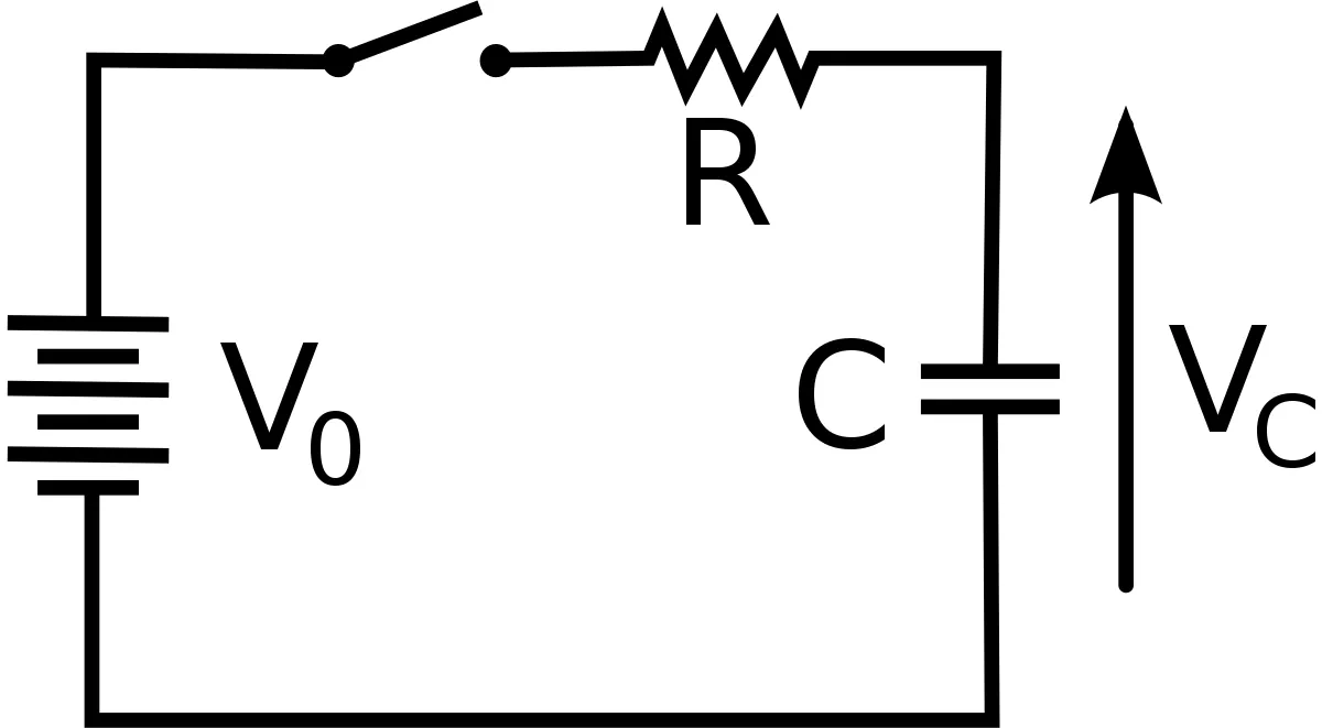
Let's start out with the circuit:
Image source: https://it.wikipedia.org/wiki/File:RC_switch.svg
The circuit contains:
- a battery with voltage V = ε
- a resistor with resistance R
- a capacitor with capacitance C
Let's consider the capacitor being uncharged (having no charge). The switch is closed "for a long time" and so the current and total charge are also zero (i = 0 , q = 0). After closing the switch at t = 0 current will start flowing into the capacitor via the resistor and so the capacitor will start charging. Having no initial voltage ( Vc = q/C = 0) the capacitor acts like being in a short circuit with the external circuit (V = ε) and the only thing that restricts this is the resistor R. By using Kirchhoff's voltage law (KVL) we have:

We can see that the voltage of the capacitor increases as the amount of charge stored increases (Vc = q/C). So, the voltage of the capacitor starts out at zero and goes to the maximum value of the EMF when fully charged, by opposing the battery. That way the current decreases from the initial value I0 = ε/R to zero as the voltage of the capacitor reaches the value of the EMF. After the current is zero the capacitor and voltage source will have the same voltage and there will be no voltage drop (IR) at the resistor R.
By integrating the previous equation we can calculate the actual charge and current flow which comes out as:

We separate the charge and time. The right integral is simple to solve and just gives t, the left one needs a substitution with u = εC - q, du = -dq and gives us:

That way the current per time is:

where τ is the time constant that we will cover shortly...
The current is I(t) = dq/dt, which means that we get:

In a similar way we can also prove that the voltage is:

cause Vc = q/C.
Time constant
As time in the graph of the charge approaches infinity, the exponential of e goes to zero and so the charge approachses the maximum charge value Q = Qε. The quantity τ = RC in seconds is known as the time constant. τ is the characteristic time of decay. It shows us that a larger resistor or capacitor causes slower charging/discharging. After approximately 4τ seconds the capacitor in a RC circuit is almosty fully charged (98%) and this period is known as the Transient period. After 5τ the capacitor is fully charged and the voltage across the capacitor (Vc) is equal to the supply voltage (Vs = ε). At this point no more current flows through the circuit and so 5τ is the Steady State period.
Note that the charging curve of a capacitor is exponential. This means that the capacitor will never become 100% fully charged and so we consider that it's fully charged after 5τ.
Discharging the capacitor
So, what happens when discharging a capacitor? When discharging we have a circuit that contains only a resistor and capacitor, and no more battery (we mostly have switches that cause this). As already told before the capacitor discharges though the resistor. Let's consider a fully charged capacitor. Using Kirchhoff's voltage law we now have:

Integrating again we will now end up with:

where Q is the initial charge of the capacitor and τ is the time constant.
The charge, current and voltage will now decrease exponentially from the initial value to zero as time approaches infinity.
The current can be found by derivating the charge with time which give us:

The voltage is again equal to q(t) / C and so:

How to apply
To apply all this knowledge you should follow the tips:
- Decide the charge of the capacitor before charging (Q0) and so just after the switch is closed.
- Decide the charge after a long time (transient and steady state period mostly)
- Use the correct initial and final charges, currents and voltages for the exponential form of q, i and v.
- The voltage across the capacitor is V = Q/C and the voltage across the other elements can be found using Kirchoff's law.
- The current through a capacitor always decays and goes to zero. The initial current is V = RI from Ohm's law.
REFERENCES:
- https://en.wikipedia.org/wiki/RC_circuit
- https://web.pa.msu.edu/courses/2000fall/phy232/lectures/rccircuits/rc.html
- https://www.electronics-tutorials.ws/rc/rc_1.html
- https://courses.lumenlearning.com/boundless-physics/chapter/rc-circuits/
- https://phys.libretexts.org/.../
Some Mathematical equations that I had in this post where drawn using quicklatex!
Previous posts about Electromagnetism
Electric fields:
Getting into Electromagnetism -> electromagnetim, electric charge, conductors, insulators, quantization
Coulomb's law with examples -> Coulomb's law, superposition principle, Coulomb constant, how to solve problems, examples
Electric fields and field lines -> Electric fields, Solving problems around Electric fields and field lines
Electric dipoles -> Electric dipole, torque, potential and field
Electric charge and field Exercises -> examples in electric charges and fields
Electric flux:
Electric flux and Gauss's law -> Electric flux, Gauss's law
Applications of Gauss's law (part 1) -> applying Gauss's law, Gauss applications
Applications of Gauss's law (part 2) -> more Gauss applications
Electric flux exercises -> examples in electric flux and Gauss's law
Electric potential:
Electric potential energy -> explanation of work-energy, electric potential energy
Calculating electric potentials -> more stuff about potential energy, potential, calculating potentials
Equipotential surfaces and potential gradient -> Equipotential surface, potential gradient
Millikan's Oil Drop Experiment -> Millikan's experiment, electronvolt
Cathode ray tubes explained using electric potential -> cathode ray tube explanation
Electric potential exercises (part 1) -> applications of potential
Electric potential exercises (part 2) -> applications of potential gradient, advanced examples
Capacitance:
Capacitors (Condensers) and Capacitance -> Capacitors, capacitance, calculating capacitance
How to solve problems around Capacitors -> combination, solving problems, simple example
Electric field energy and density -> Electric field energy, energy density
Dielectric materials -> Dielectrics, dielectric constant, permittivity and strength, how to solve problems
Electric capacitance exercises -> examples in capacitance, energy density and dielectrics
Current, resistance and EMF:
Electric current -> Electric current, current density
Electrical resistivity and conductivity -> Electrical resistivity, conductivity, thermal coefficient of resistivity, hyperconductivity
Electric resistance -> Resistance, temperature, resistors
Electromotive Force (EMF) and Internal resistance -> Electromotive force, internal resistance
Power and Wattage of Electronic Circuits -> Power in general, power/wattage of electronic circuits
Electric current, resistance and emf exercises -> exampes in all those topics
Direct current (DC) circuits:
Resistor Combinations -> Resistor combinations, how to solve problems
Kirchhoff's laws with applications -> Kirchhoff's laws, how to solve problems, applications
Electrical measuring instruments -> what are they?, types list, getting into some of them, an application
And this is actually it for today's post and I hope that you enjoyed it!
Next time we will get into R-C circuit exercises!
Bye bye!