
Hello it's me again! Today we will talk about the software called ModelSim from Altera that I will use for Simulation/Compiling in all our VHDL posts! You can download the Starter Edition from here and so let's get into some Basic things that you need to know to get started with this program!
Interface Startup:
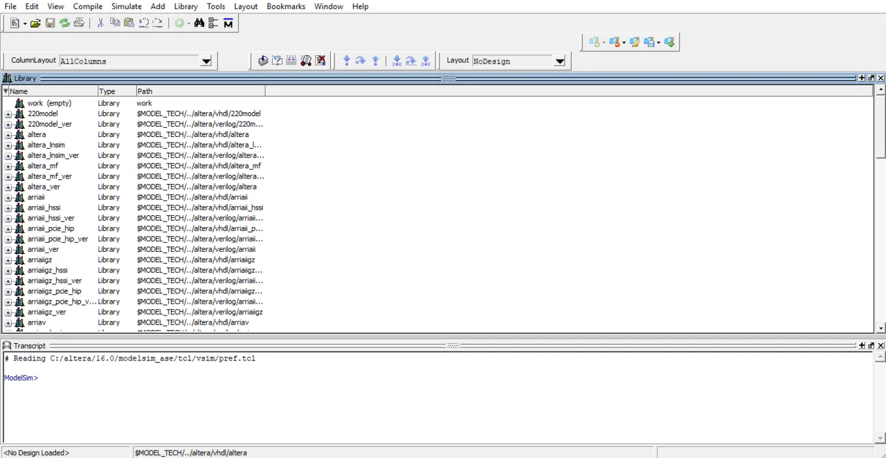
The Interface is actually pretty simple! It consists of 3 Basic Things: Toolbar, Libraries, Transcript (Command Line). We will mostly use the Transcript for doing stuff directly using simple Commands, without searching the Toolbar for all the stuff. We will also create our own library/project called work instead of using those that are given to us every time we use a new vhdl code folder.
So, the main thing to worry about the first time we start up the Program and everytime we change directory for our vhdl codes is creating/mapping our own library. This can be done this way:

We first change directory using cd and putting in the directory we want to go to, or we can also go to the Toolbar Menu and choose File/Change Directory (I prefer this way). Then we have to create a new library called work using vlib work and then we override the library using vmap work work to the already existing one.
Compiling and Running VHDL Codes:
The next thing that you need to know is how we compile and "run" a VHDL Code. When having a VHDL Code that contains many others inside as Components (more into that some posts later on) we will have to compiler first the Component VHDL Codes and then the final VHDL Code that contains them.
To Compile we use the instruction vcom and after that the name of our vhdl code file. So, to compile the and2_gate we had last time and supposing the name of the file is and2_gate.vhd we then have to write down this:
vcom and2_gate.vhd
To Run/Simulate the Circuit we use vsim and the name of the entity! So, simulation of the previous and2_gate can be done using:
vsim and2_gate
So, all that inside of Modelsim looks like this:
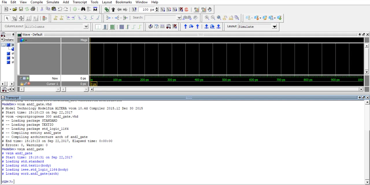
You can see that after starting the simulation our Interface changes and the Library is being replaced by Wave that will represent Waveforms of anything that we want to show off from the Circuit's Inputs/Outputs etc.
Circuit Simulation:
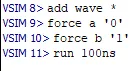
Circuit Simulation will again be done using Commands mostly inside of the Transcript. What I like to do is use a command to insert all inputs and outputs of the Circuit as Waveforms and then I start giving values to the Inputs and run the Circuit for some nanoseconds to get a result.
To add one input or output to the Waveforms we use the command add wave and then the name of the input/output. To insert all inputs and outputs we use:
add wave * (I like using it a lot).
To set the value of an input we use the command force. This command gets the name of the input/signal and the value as arguments. When having a single bit we use '0' or '1' and when having more then one bits we put the value inside of two ". So, to put a value of 0 to input a and a value of 1 to input b we use:
force a '0'
force b '1'
Lastly to run our Circuit Simulation we use the command run followed by nanoseconds (ns) or picoseconds (ps) mostly. So, to run our Circuit for 100ns we do:
run 100ns
This looks like this in Modelsim:
Transcript:
Wave:
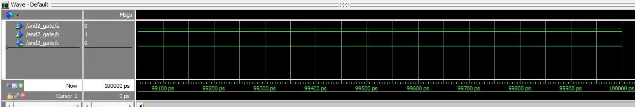
You can see that with a = 0 and b = 1 we have an output c = 0 as expected by an and gate.
One last thing about this simulation window I want to point out is how we can force a value in another way and use a Clock Input so that everything is inside of this Post, but I will tell it again when we get into Sequential Circuits.
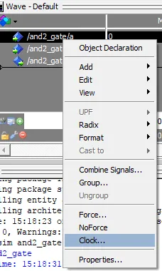
When right-clicking on an input inside of Wave we can see that there are Options for Force Input and also Clock Input. That's exactly how we can change the Input value without the use of Commands!
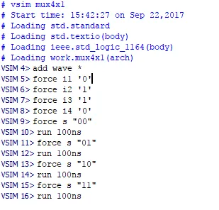
By doing all this we actually ran the Code from previous Time! Let's get into another example running also the mux 4x1 code from previous time!
Example:
I already have the library set up and so I only have to compile and simulate the circuit! Let's make I0, I1, I2, I3 have the values 0, 1, 1, 0 and try out all the different S input combinations. I only need to show you the Transcript and the Waveforms!
Transcript:

Wave:

You can hopefully see that that we don't have to re-force the inputs, but they stay like that "forever" and so we only have to change the input s! We also see that the Output is correct and follows exactly our Code and the Truth Table of an 4x1 multiplexer.
And this is actually it! Hope you enjoyed this post and learned something about ModelSim!
Next time in VHDL we will get into all the different kinds of Coding Models (Behavioral, Dataflow, Structural) that we can use to write a Code! I will have Examples of same Circuits in different Models. First simple Gates and afterwards more advanced stuff!
Bye!