Hey, its me! This time we will implement Simple Circuits using Gates starting off with specific given things that they have given to us. I will start with the simplest one that is an already simplified Function, continue on with a Function in Minterms and end our talk with an Truth Table. So, let's get straight into it!
Function is given:
When the function is given we simply have to translate it into a Circuit the same way we did it in "From Function to Circuit". So, let's get a function and translate it into a Circuit and see what kind of Outputs we get and try to explain them in some Input Combinations!
Let's take this Function for example:
F(A, B, C) = AB +A'C + (B+C)'
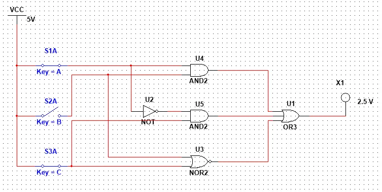
As we said in the post I was talking about earlier, we will have a OR-3 Gate at the end and the Inputs of it will be the Ouputs of 2 AND Gates and an NOR Gate. Also, the A Input of the second AND will be inverted with a NOT. So, our Circuit will contain 1 OR-3 Gate, 2 AND Gates, 1 NOR Gate and 1 NOT Gate.
So, our Circuit looks like this:
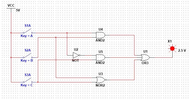
Let's now try to see what makes the Circuit get an Output of 0! The Function will have an Output of 0, when all those Gates have an Output of 0. I see 2 of those directly. One is A = C = 0 and B = 1 that makes the NOR Gate's Output 0 and the others remain 0. Another one is A = C = 1 and B = 0 that makes the NOR Gate have an Output of 0. the first AND Gate remain 0 and the second one also remain 0, cause one of those Inputs is inverted. Let's try those out!
As you can see it worked! I tried all the possible 8 Combinations and it's crazy that only those 2 Combinations give an Output of 0. So, what can we do with that information? We can implement the Function using two Maxterms!
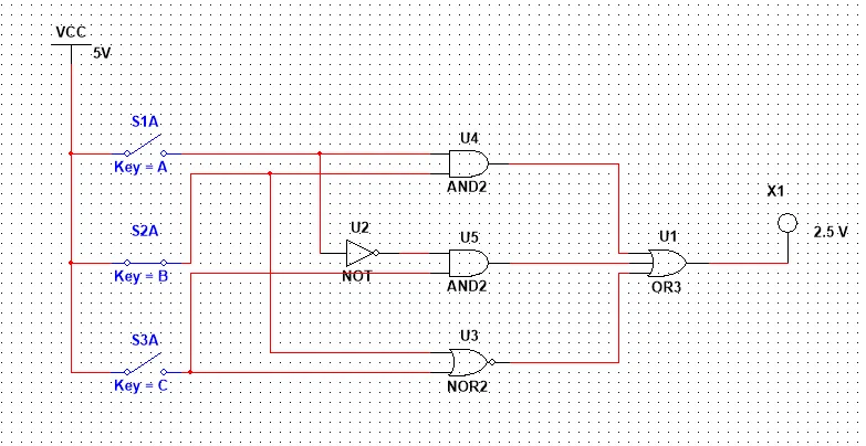
So, the Function using Maxterms now would look like this:
F(A, B, C) = (A + B' + C)(A' + B + C')
This circuit would contain 3 NOT Gates, 2 OR-3 Gates and 1 AND Gate and the number of Gates is more then before, because of all those Invertions!
We could continue this process on and create millions of Circuits that follow the same Truth Table!
Minterm are given:
Let's now create a Circuit when the Function is given to us with Minterm, as we did yesterday in the Tabular Method! But, we will not use the Tabular Method, but a Karnaugh Map, cause the number of Input Variables is 4 and Karnaugh Map works great when the number is 4 or lower!
Let's take the Function we had last time in the Tabular Method, that contained 4 Variables!
F(A, B, C, D) = Σ(0, 1, 2, 3, 5, 7, 8, 10, 12, 13, 15)
Do you remember the Trick I told you when talking about K-Maps? Well in each row we simply put the Outputs in opposite order and when we are in a 4-Variable K-Map we also change the two row's position like that:
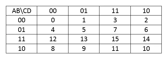
Let's put the 1's in the corresponding places shown in the representation we have and solve the K-Map by grouping the Minterms!

In Group Red only A and B stay the same and at 0, so we have A'B'.
In Group Yellow only B and D stay the same at 1, so we have BD.
In Group Green A stays the same in 1 and C and D the same in 0, so we have AC'D'.
The Indigo one is alone and is the minterm AB'CD'.
So, our Function is:
F(A, B, C, D) = A'B' + BD + AC'D' + AB'CD'
We again end up with another Function then in the Tabular Method and it's not the best one!
Let's try it again and put 15 inside of a group grouping the Cornes and let's also put some Minterms in more than one Groups!
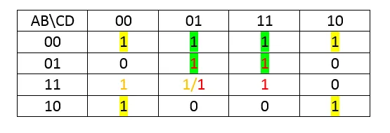
So, this time our Function would look like this:
F(A, B, C, D) = B'D' + A'D + BD + ABC'
That way we end up with one of the best Solutions that we had last time in the Tabular Method!
I also said that time that BD + B'D' can we made into an XNOR Gate.
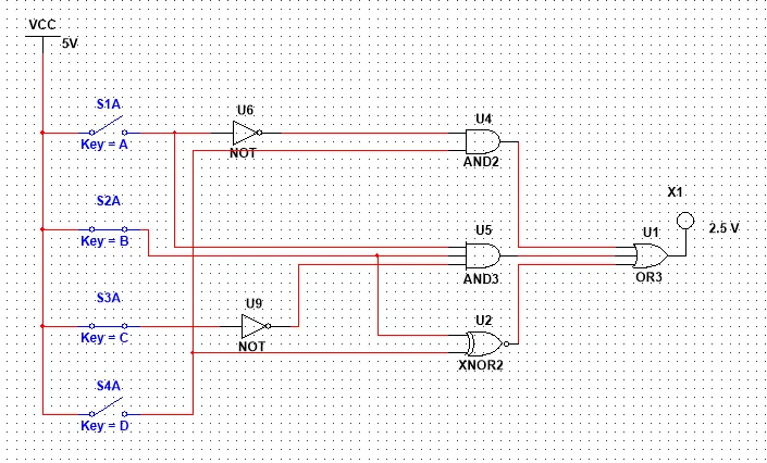
So, let's use this Function to create our Circuit:
F(A, B, C, D) = A'D + ABC' + BXNORD
Let's now also make the Circuit and try out some of the Input Combinations!

With Input 0000 that represents Minterm 0 we have Output 1 as expected!
With Input 0110 that represents Maxterm 6 and is not a Minterm we have an Output of 0!

With Input 1101 that represents Minterm 13 we have an Output of 1 as expected!
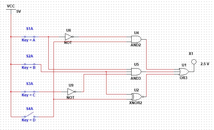
With Input 1110 that represents Maxterm 14 we have an Output of 0!
I tried all the Combinations and the Circuit matched exactly to the Function Minterm Representation we used to create the Circuit!
Truthtable is given:
Let's now lastly start off with an Truthtable and create a Circuit after getting the simplified function! Let's use a simple concept so that we have to create the Truthtable from an given explanation/definition of the way the function should work!
Let's create a Circuit with 3 Inputs, were the Output is 1 only when the number of 1's is greater then the number of 0's in the Inputs.
The Truth Table is simple and looks like this:
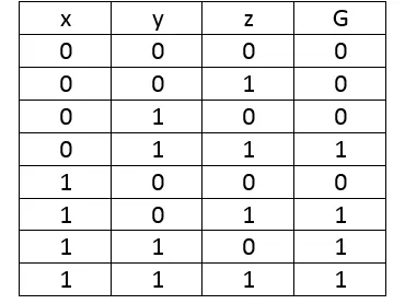
The Karnaugh Map is also pretty simple to make and solve and looks like this:

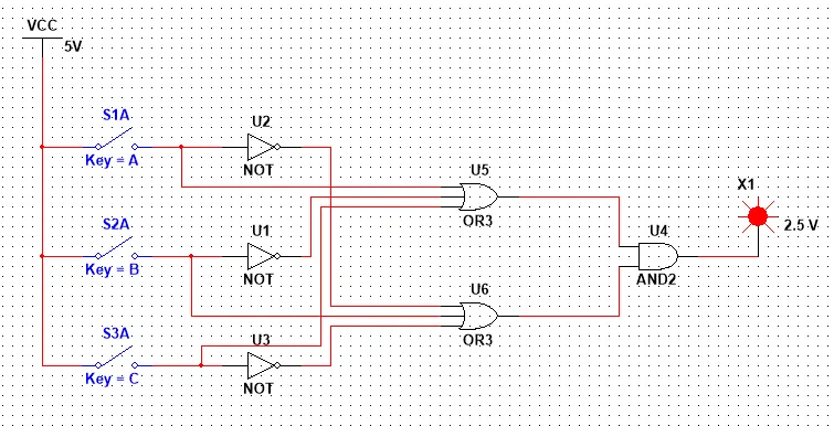
So, our final Function looks like this:
G(x, y, z)=yz+xz+xy
And the Circuit like this:

We're the Output is 1 only when 2 or more of the Inputs are active!
This is actually it! Hope you enjoyed it and understood better the concept of creation!
Next time in Multisim we will implement Adder Circuits!
Bye!