Hello my friends I'm back! I had a lot to do in the weekend so I had no time for posting and I also wanted to check out other people in steemit! Today we will talk about Adder Circuits implemented in Multisim. You can check the Theory for those here. I will start with Half and Full Adders, continue on with an N-bit Adder and also create an N-bit Subber! So, let's get started!
Half Adder:
An Half Adder works pretty simple. It adds two 1-bit numbers and gives us the result and carry, cause we can have a 2-bit answer! I already talked about the implementation in Theory, so let's get directly into the implementation in Multisim!
We will use the XOR and AND Gate implementation, having the Result S be the output of a XOR Gate and the Carry C be the output of an AND Gate.

When only one of the Inputs is 1, we have S = 1, C = 0
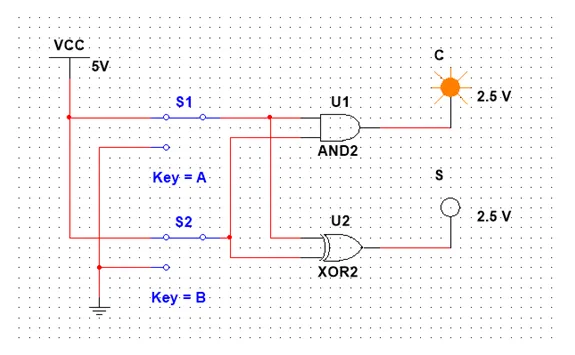
When both are 1 our Output is C = 1, S = 0
And as you already know, when both are 0 we have the Outputs be also 0.
Full Adder:
To create an Full Adder that has 3 Inputs and 2 Outputs we will use the implementation we proofed using Karnaugh Map in Theory and another implementation that uses 2 Half Adders and 1 OR Gate!
The first implementation looks like this:
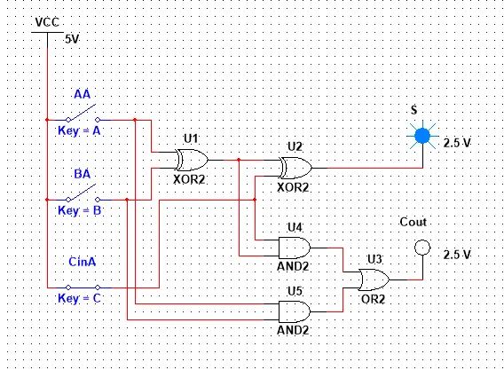
When 1 Input is 1 then S = 1, Cout = 0

When 2 Inputs are 1 then S = 0, Cout = 1

When all 3 Inputs are 1 then we have S = Cout = 1
And you can also think about what happens when all are 0, then the 2 Outputs are also 0!
Let's now think about the second implementation. If you think about the implementation of a Half Adder you will see that it contains an AND and a XOR Gate. So, looking into the first implementation we can see that we can represents this stuff in our Circuit as a Half Adder. That way we will have 2 Half Adders and 1 OR Gate in our Circuit!
So, our implementation looks like this:

When 1 Inputs is 1 then S = 1, Cout = 0

When 2 Inputs are 1 the Cout = 1, S = 0
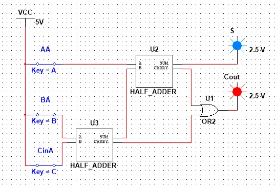
When all 3 Inputs are 1 then we have S = Cout = 1
And when all are 0 our Outputs are 0 again.
So, both implementations define the same Circuit and the second one is just an simplification using an Circuit we already know as an Sub-Circuit!
N-bit Adder:
Let's now get into how we implement a N-bit Adder! Let's create a simple 3-bit Adder using 1 Half Adder and 2 Full Adders and check the Output for some Inputs! We will have to read our Output in reverse starting from the Final Carry and continuing on with Sum2, Sum1, Sum0...

000 + 000 = 0000 (0 + 0 = 0)

111 + 111 = 1110 (7 + 7 = 14)

100 + 111 = 1011 (4 + 7 = 11)
N-Bit Subber:
As I already showed you in Theory a N-bit Subber is actually an N-Bit Adder with some tweaking in the Inputs! Using that tweaking we successfully add the 1st number with the 2nd number's 2's complement and make a sub into an add! We will also don't use the last digit from the carry in the Output as you might remember from Numeral Systems.
So, an 3-bit Subber would look like this:

101 - 010 = 011 (5 - 2 = 3) and we have Cout = 0 that means the output is positive!

111 - 110 = 001 (7 - 6 = 1) and Cout = 0 that means outputs is positive!
When the result is negative you will have to inverse the output and add 1 (2's complement)
So, for example 110 - 111 = 111 (6 - 7 = -1) and Cout = 1 means we have 111 -> 000 + 1 = 1 that is negative so result is -1! And you can do it for all numbers!
This is actually it! Hope you enjoyed it!
Next time in Multisim we will implement the Multiplexer, Encoder and Decoder Circuits we talked about in Theory and next time in Theory I will talk about Statetable simplification before getting into Sequential Circuits in Multisim that is also our last Multisim post!
Bye!