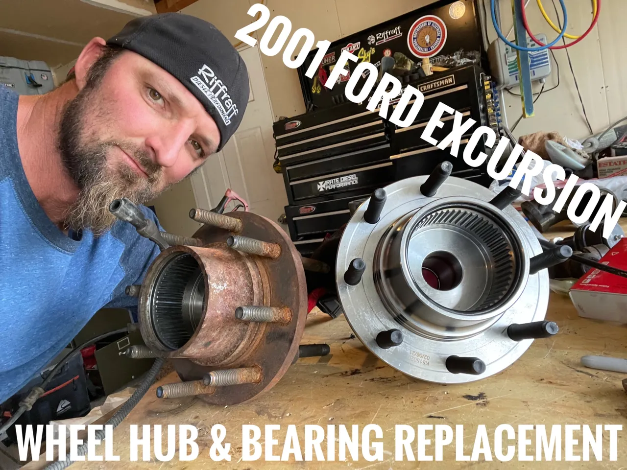
This is gonna be the first part of a series I am putting together about rebuilding the front axle on my 2001 Ford Excursion. This process will also work on 1999-2005 F250/350 and 2000-2005 Ford Excursions. I’m gonna start with the Wheel Hub & Bearing then move deeper into the front axle as I replace ball joints, U-joints, Axle dust & Vacuum Seals, tie rods and tie rod ends.
Wheel Hub & Bearing Replacement
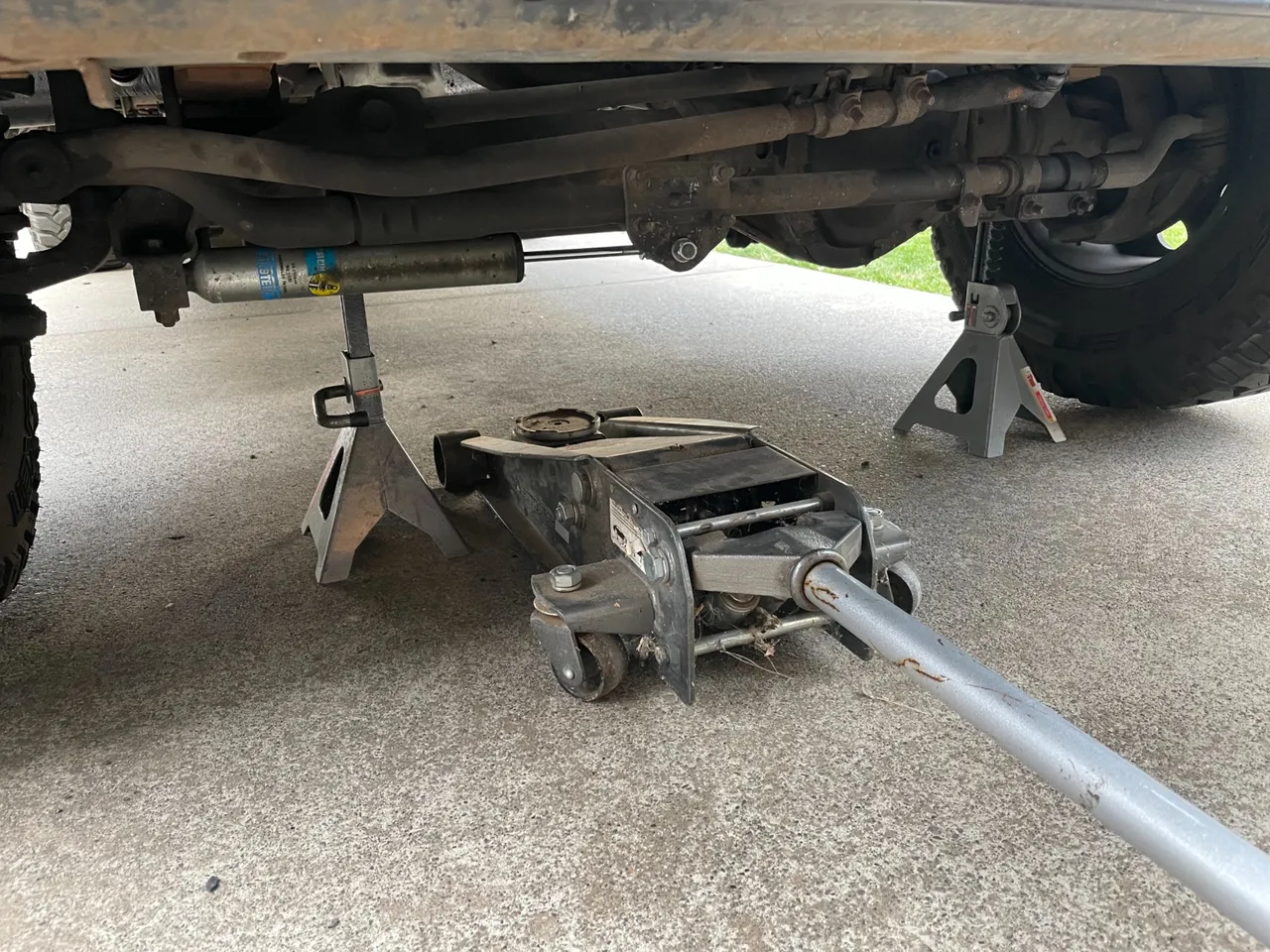
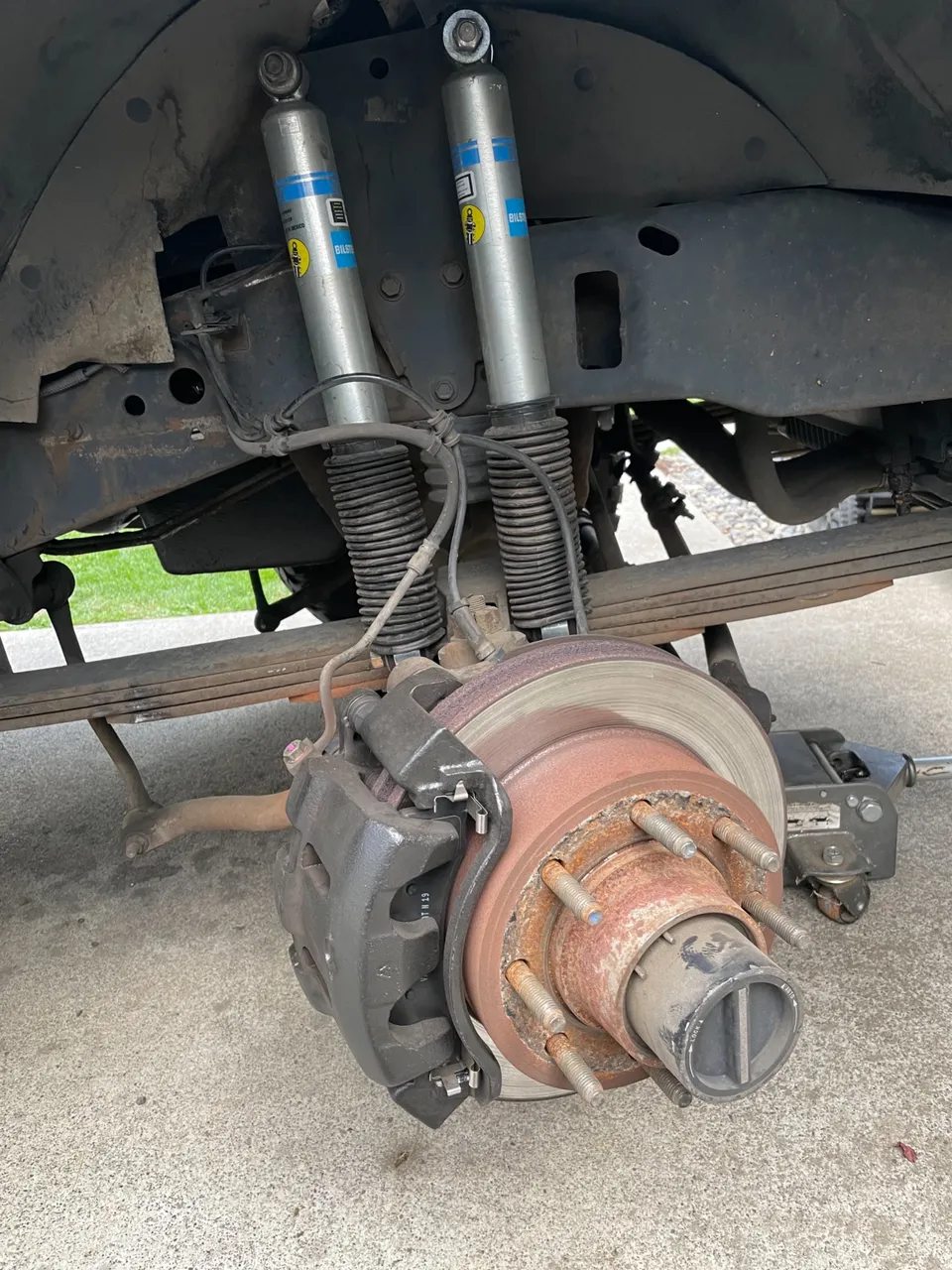
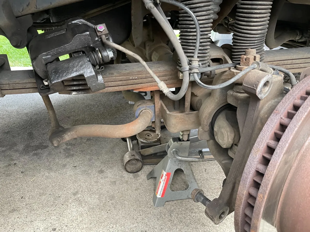
Since I am working on the front end and it is going to be completely off the ground, I always set the emergency brake and throw a block of wood behind the rear tires. Then jack up the front of the vehicle and put it on jack stands. Ensuring the tires are just an inch or two off the ground. There is no need to take this lifted truck any higher.
Using a 21mm socket remove the lug nuts and pull off the wheel
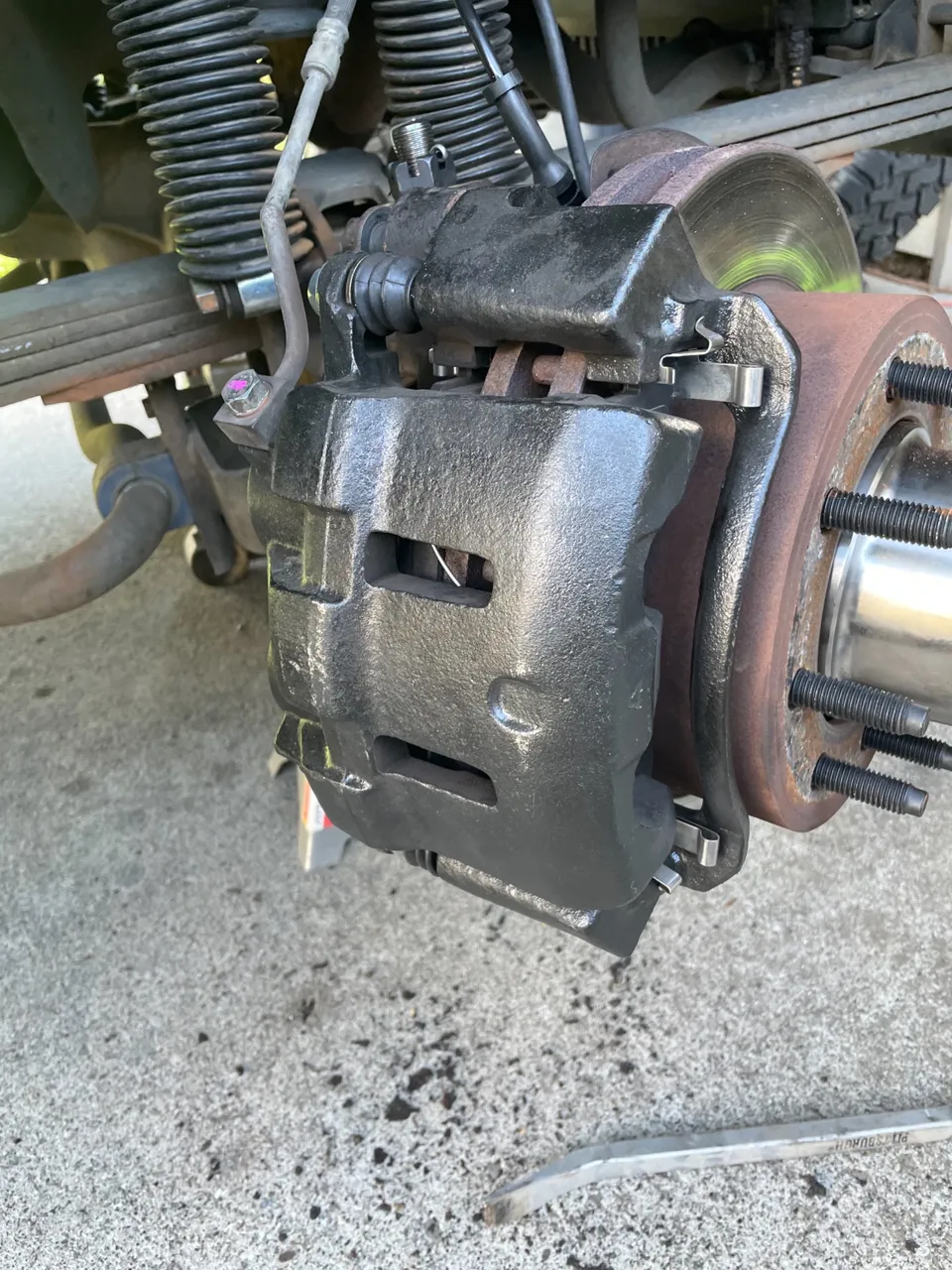
The next part that needs to be removed is the brake caliper and it’s bracket
To do this turn the steering wheel all the way to the right or left depending on what side you are on. The bolts that need to be removed are located behind the rotor and toward the rear of the vehicle. These also can be removed with a 21mm socket.
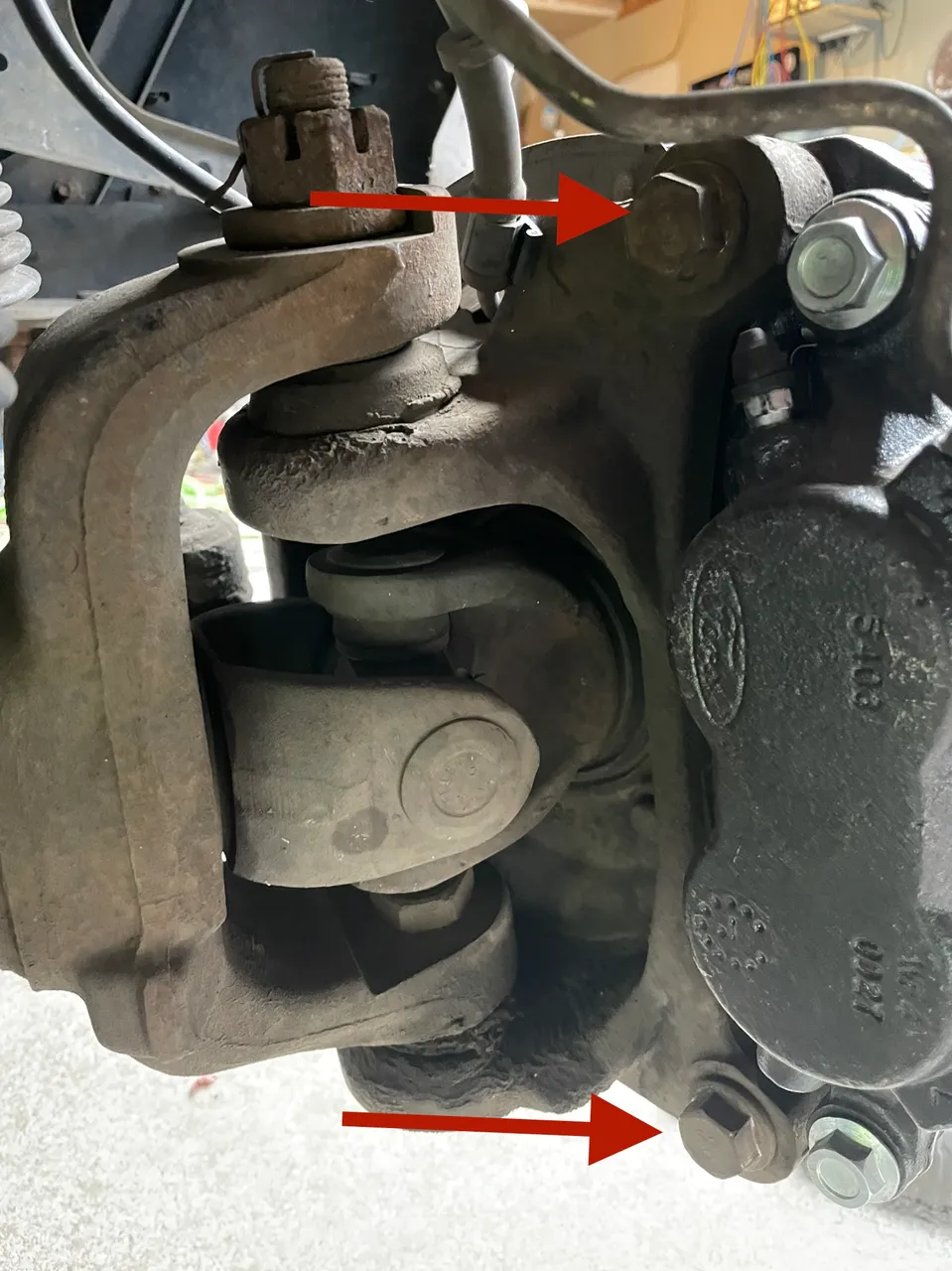
Remove the caliper and be sure not to drop it or just let it hang. This can damage the brake lines. Find a place to secure it so that it doesn’t fall
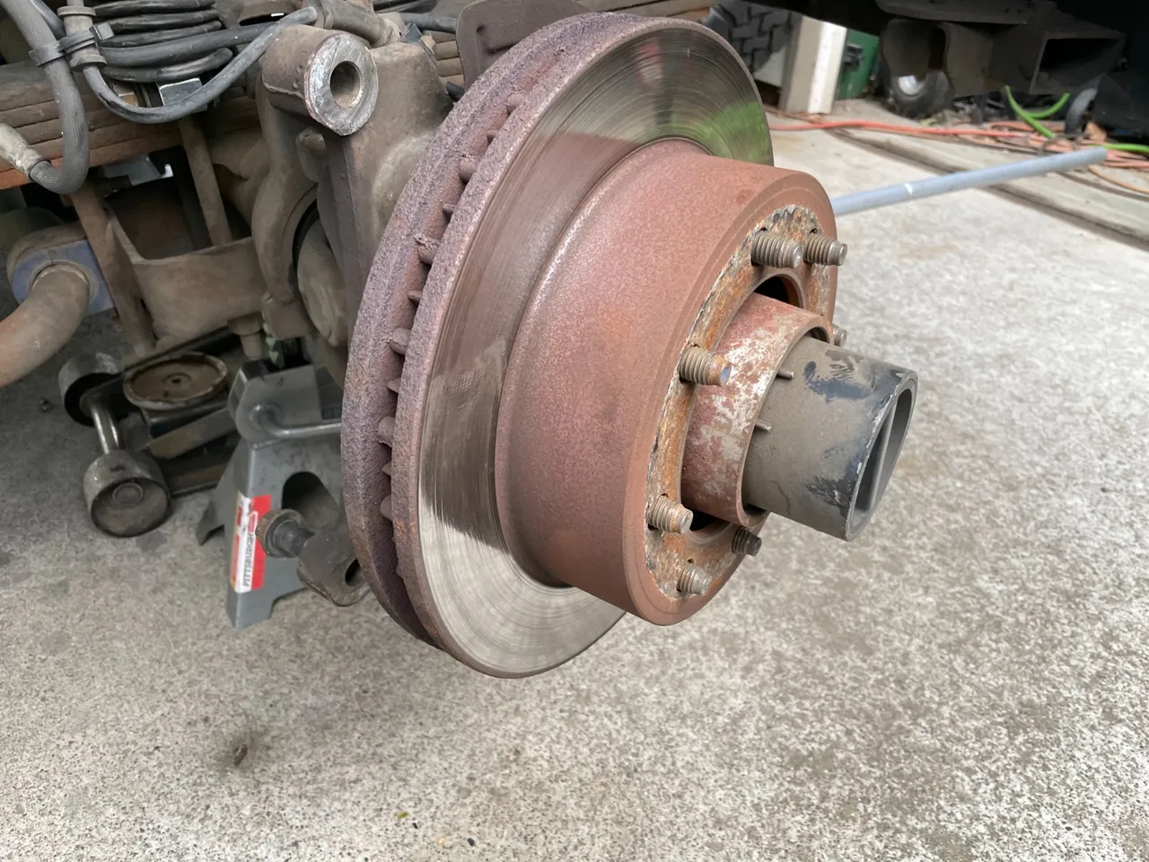
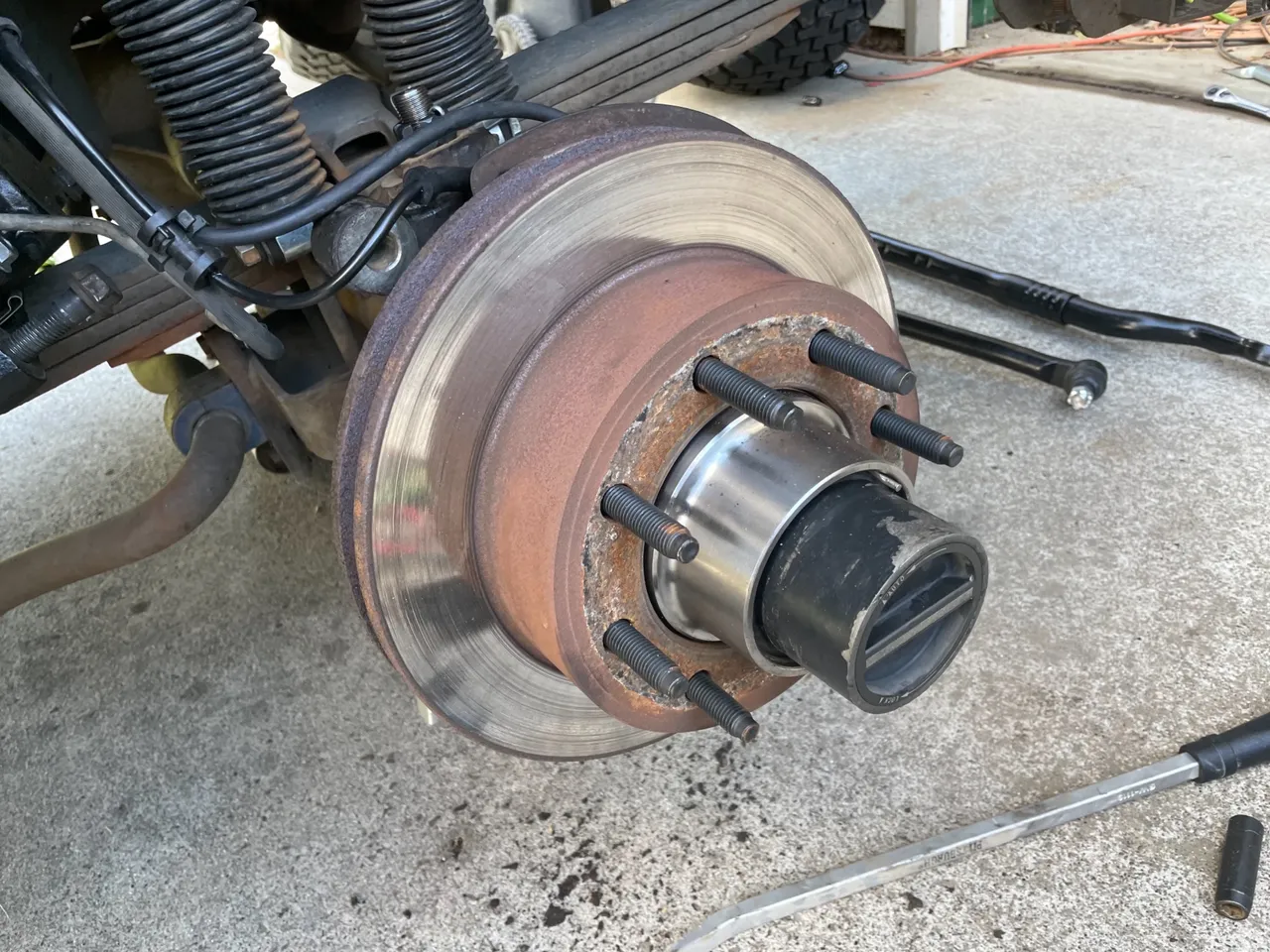
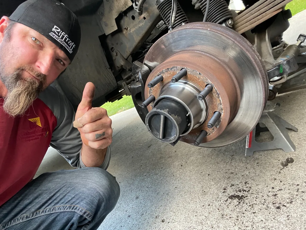
Then remove the brake rotor by simply sliding off of the lug bolts
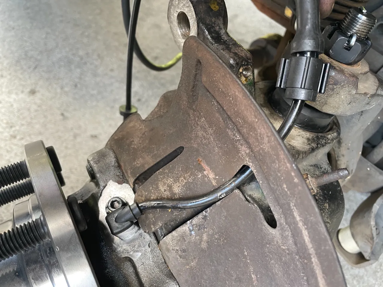
On the top of the steering knuckle is the ABS speed sensor.
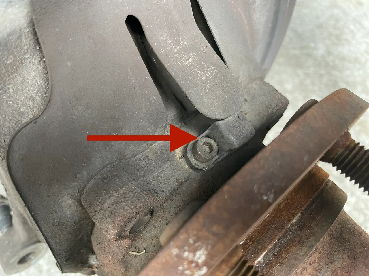
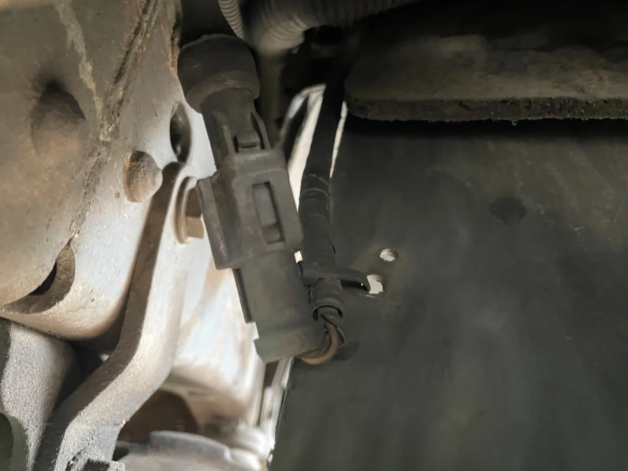
Follow the cable all the way back to the plug that sits back behind the mud flap. Remove the cable from all the clips and unplug it. There is one 8mm bolt that holds a clip in place on the outer knuckle
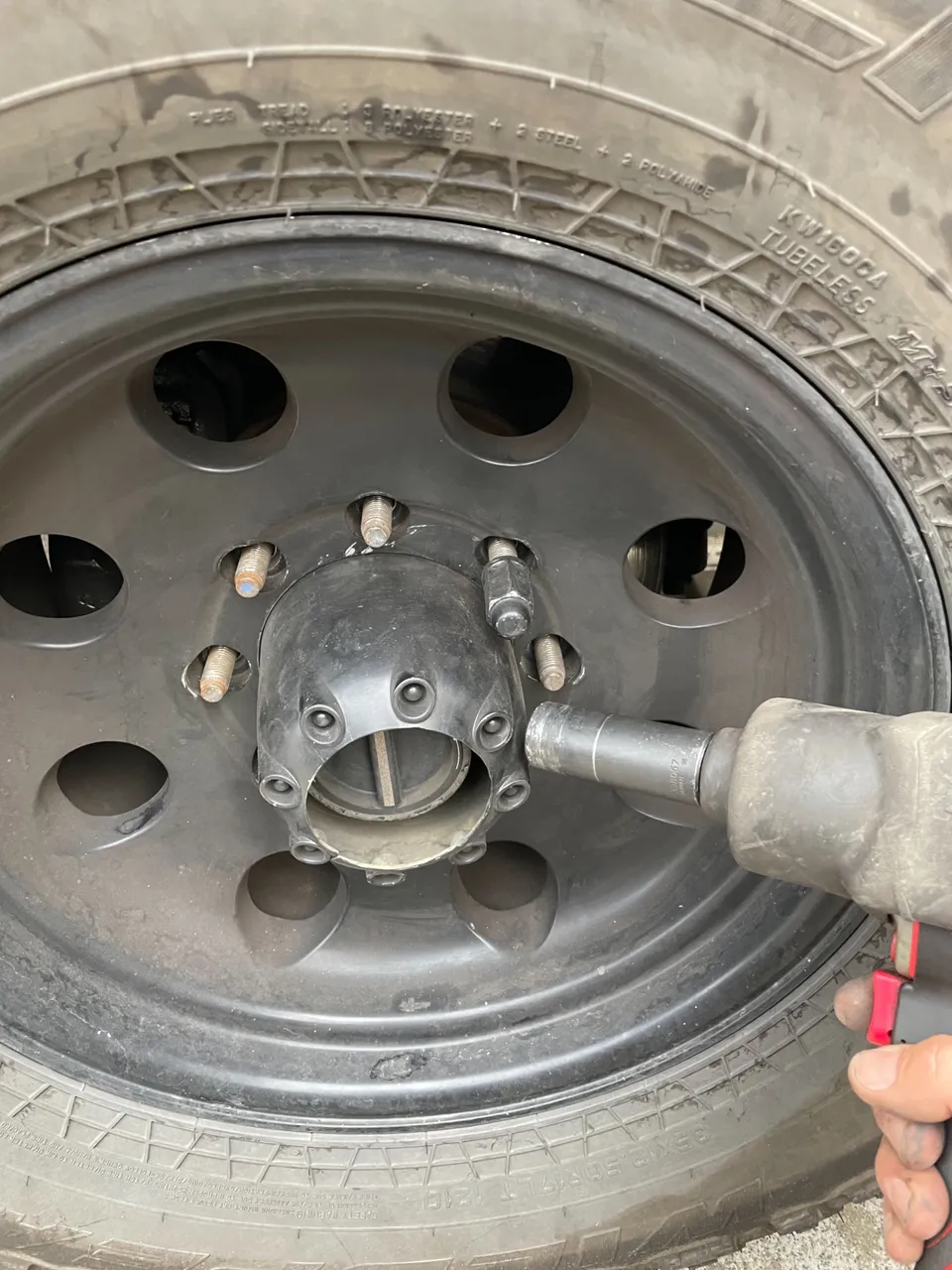
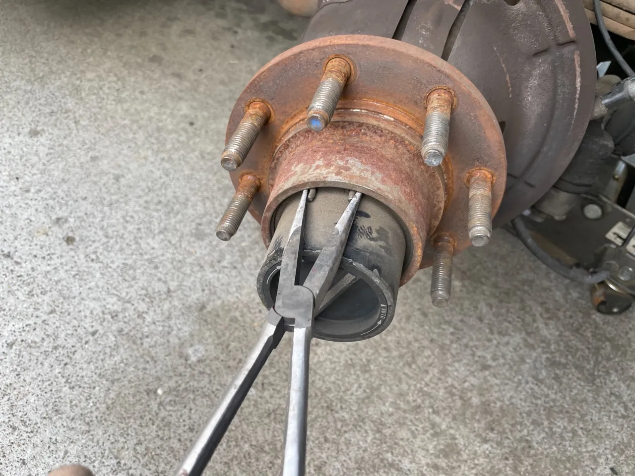
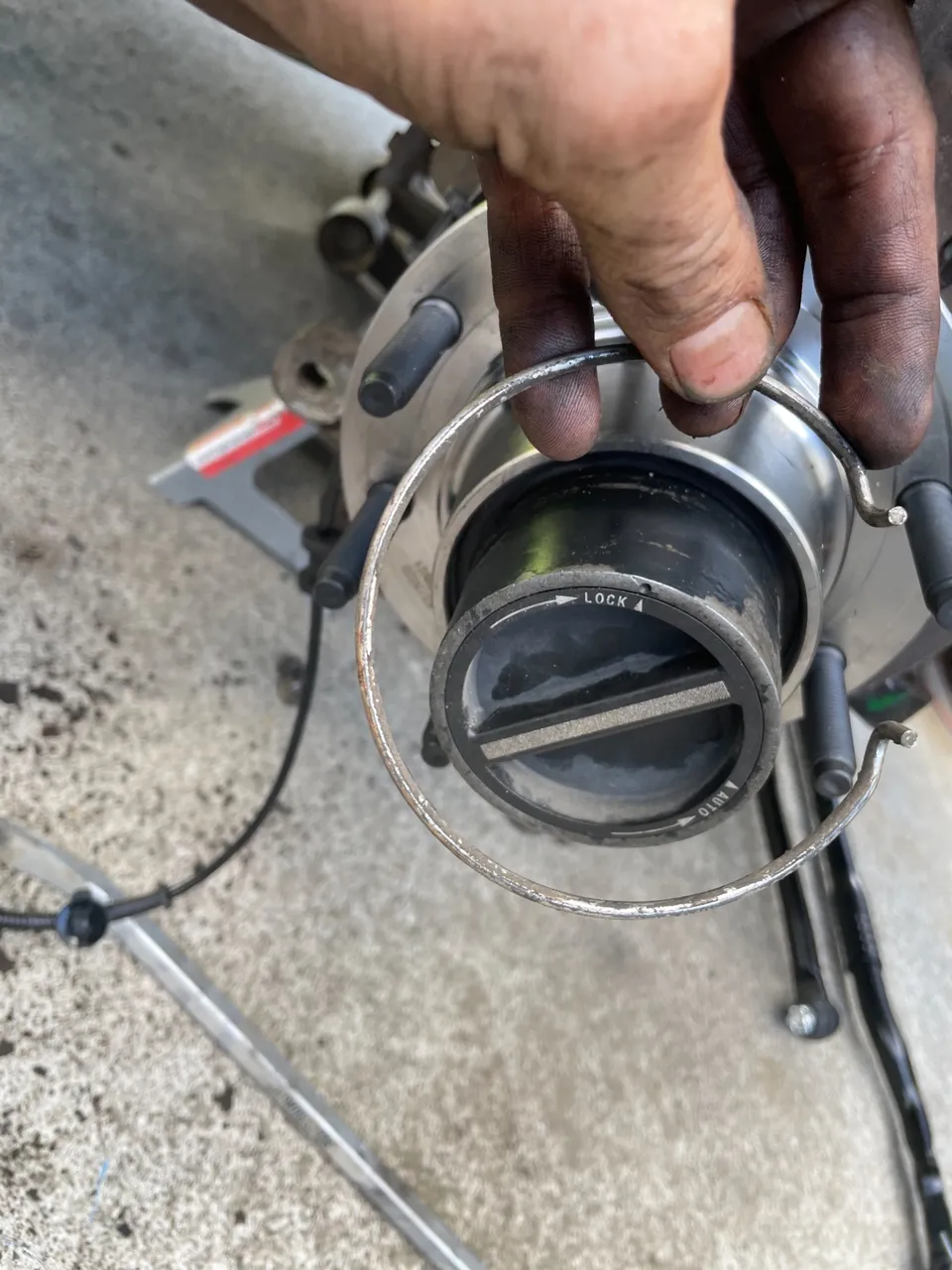
The next part that needs to be removed is the manual switch to lock in the hubs for 4 wheel drive. These hubs also have an auto locking feature that uses vacuum to lock in the front hubs via a switch in the cab. So if your vacuum system malfunctions you can get out and manually lock in the hubs engaging the front axles.
To remove it there is a retaining clip that just needs to be squeezed together with some pliers and slid off the end
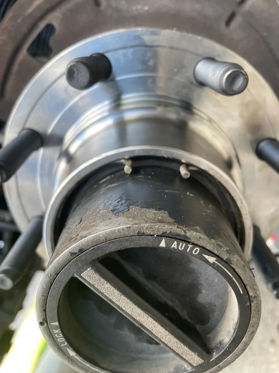
Then wiggle and slide the auto locking hub assembly out.
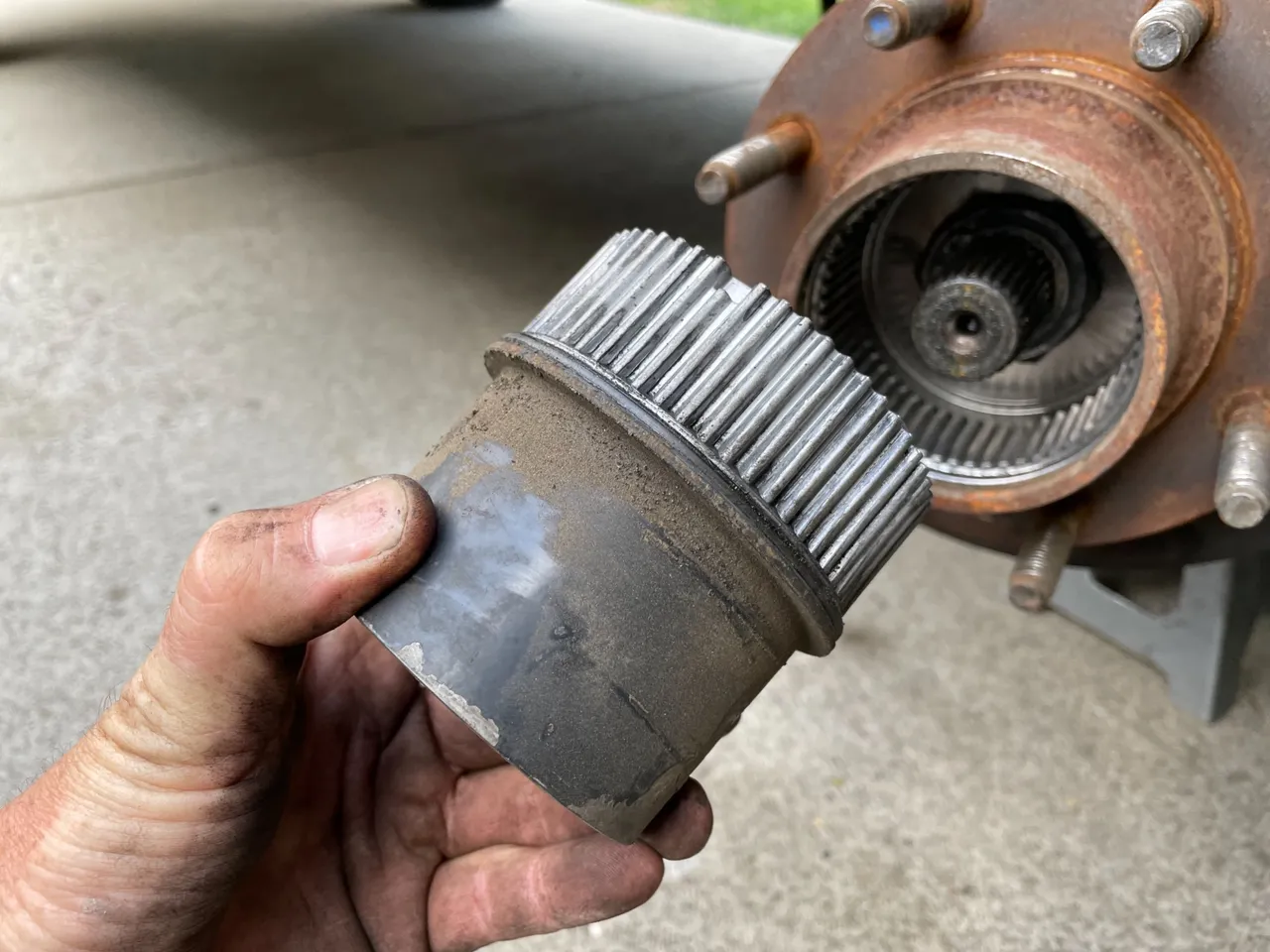
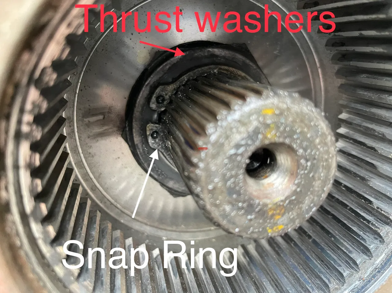
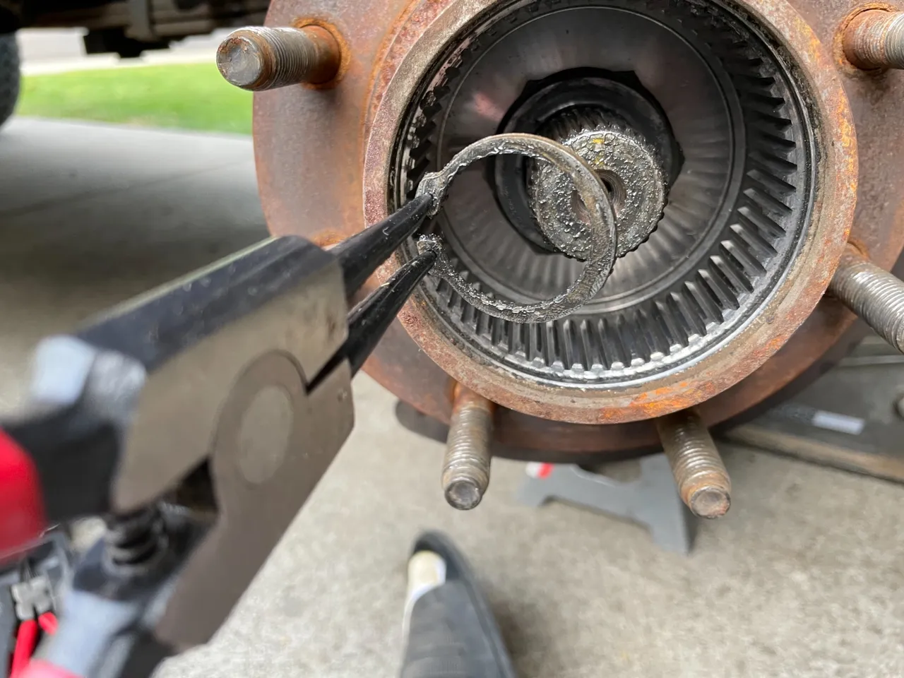
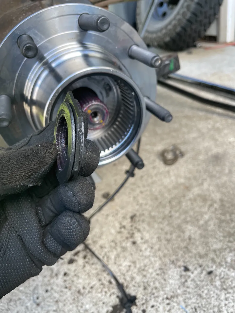
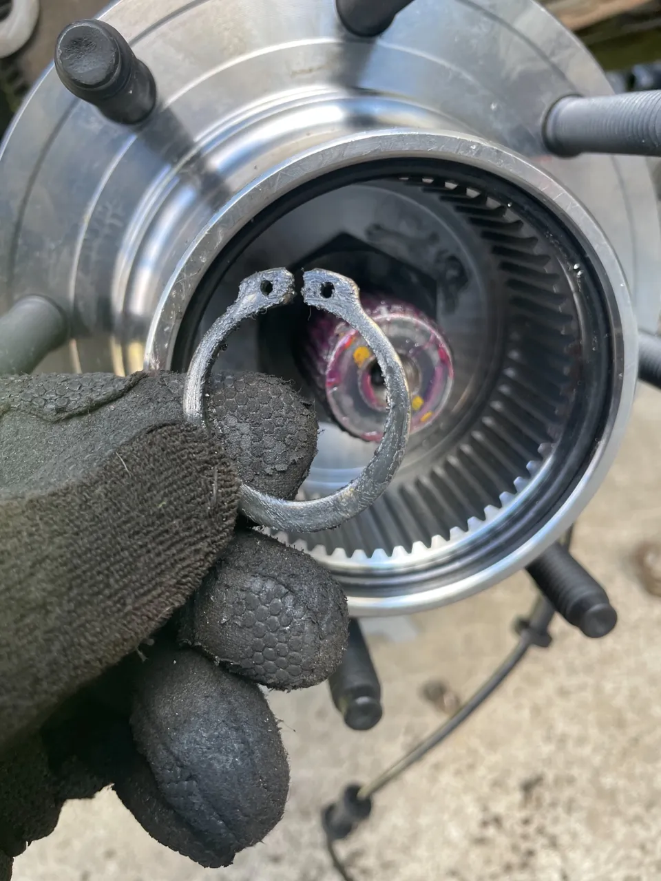
Inside the wheel hub there is a snap ring with 3 thrust washers behind it. Using a set of snap ring pliers remove the snap ring and fish out the thrust washers. Make sure they go back in the same way.
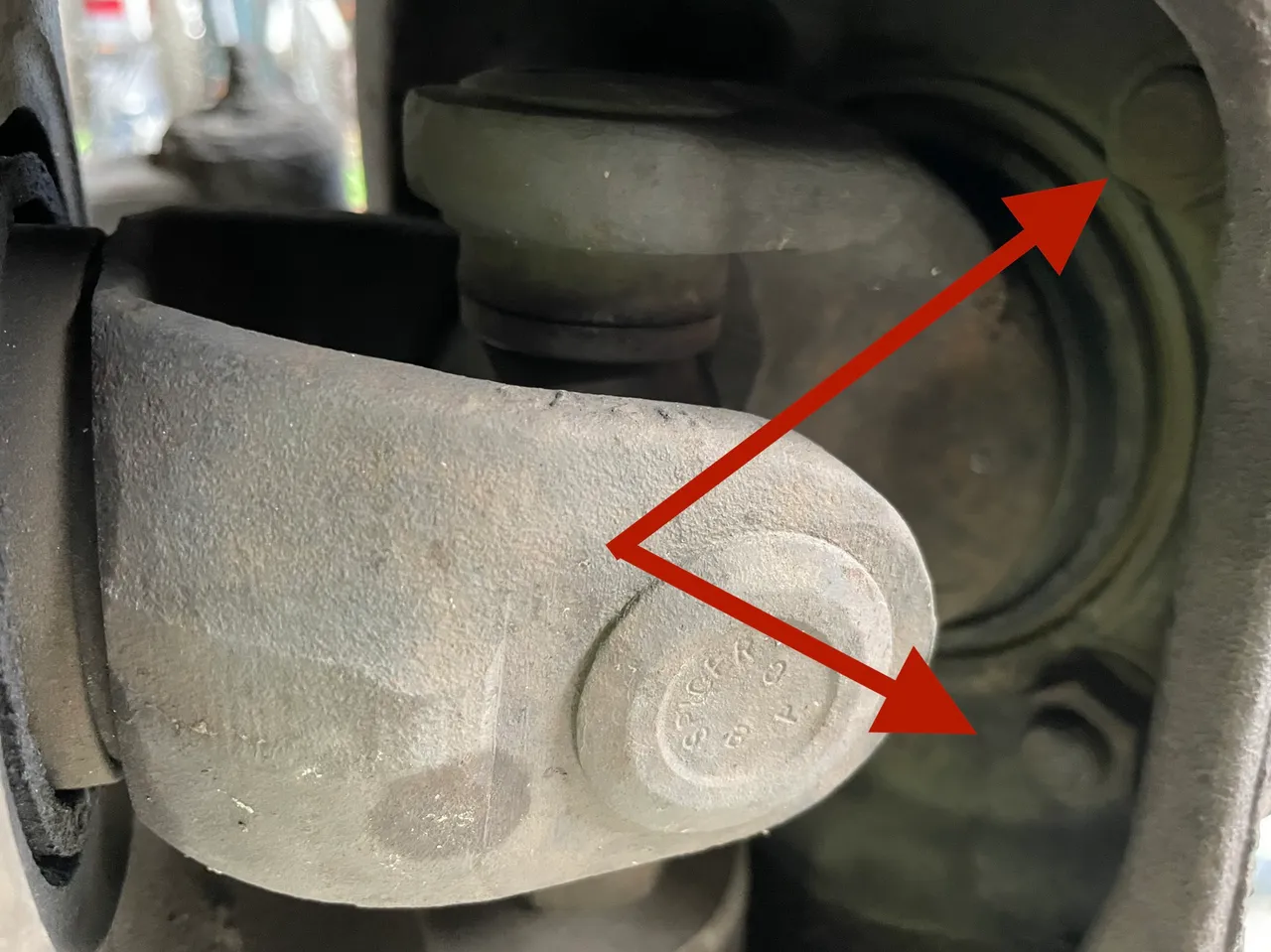
There are only 4 more nuts that need to be removed in order for the hub/bearing to be removed. They are located inside the outer steering knuckle. In order to access them you need to turn the steering wheel all the way left and then all the way to the right. This will give you room to get a socket in there. Rotating the axle also helps to get the u-joint out of the way
Using a 21mm socket remove the 4 nuts holing the hub/bearing in place. You may need a bit of persuasion in order to get them loose. So get a big hammer and possibly a breaker bar.
With those 4 nuts removed you are most likely gonna need to beat on the hub/bearing a bit in order to break it lose. I use this 3 pound mini sledge hammer a lot when it comes to breaking things loose. It’s kind of like my Thor hammer
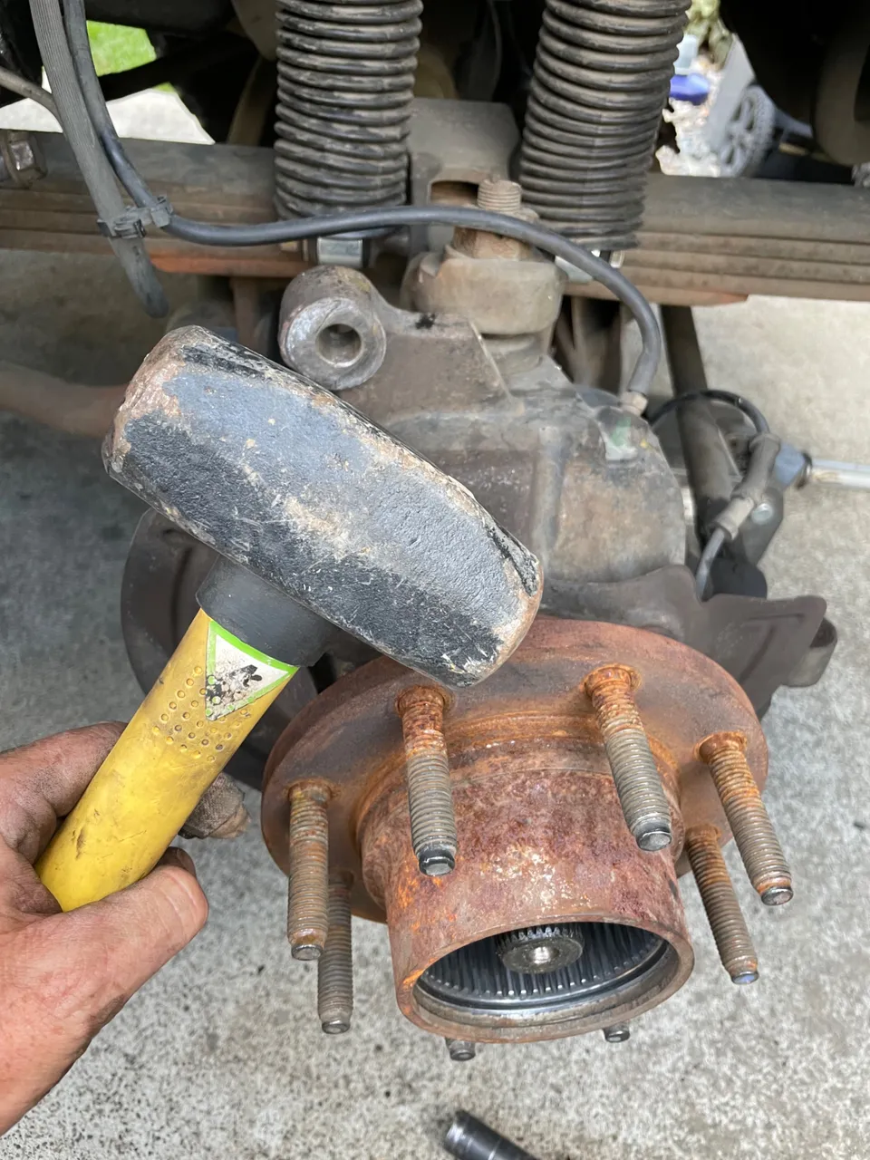
Don’t worry about breaking anything and just give it a few good blows with the sledge in all directions. This will brake away any rust that has developed and you should be able to wiggle it out.
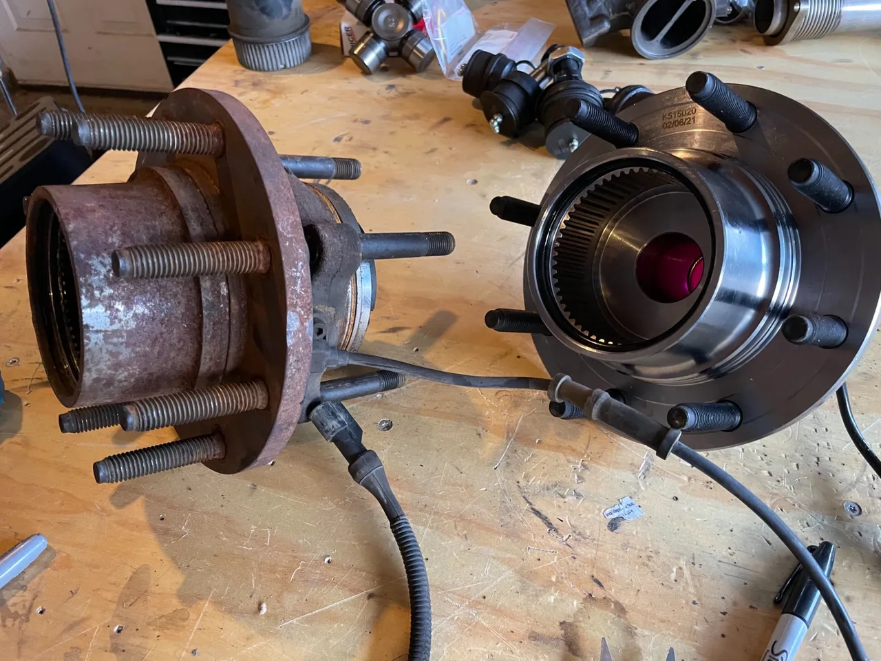
The Install
Now we are ready to install the new hub/bearing. Well almost… Clean the surface area where the hub and outer knuckle come together with a wire brush. Get all the rust and whatever other crud off of there. You always want a clean mounting surface.
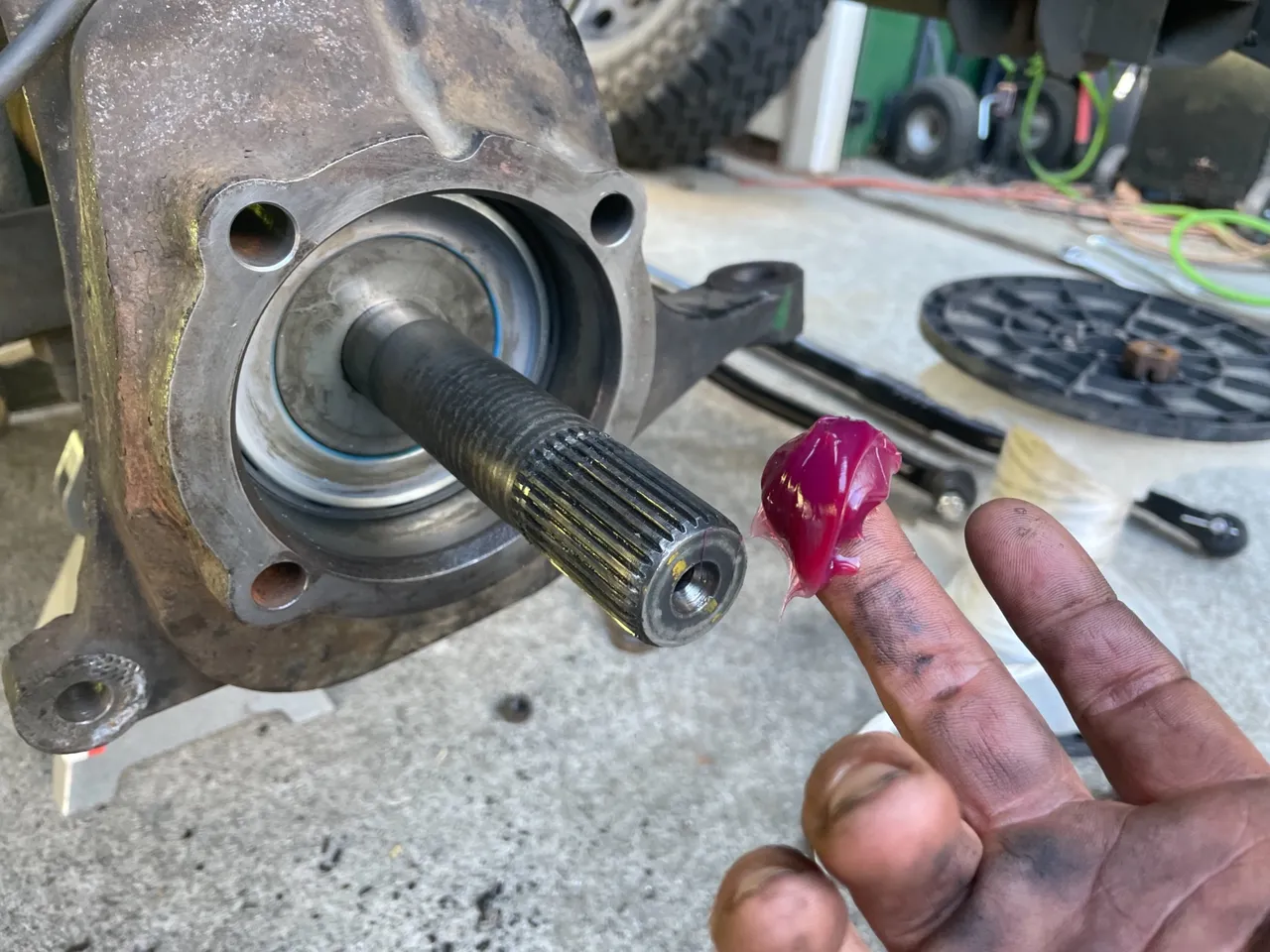
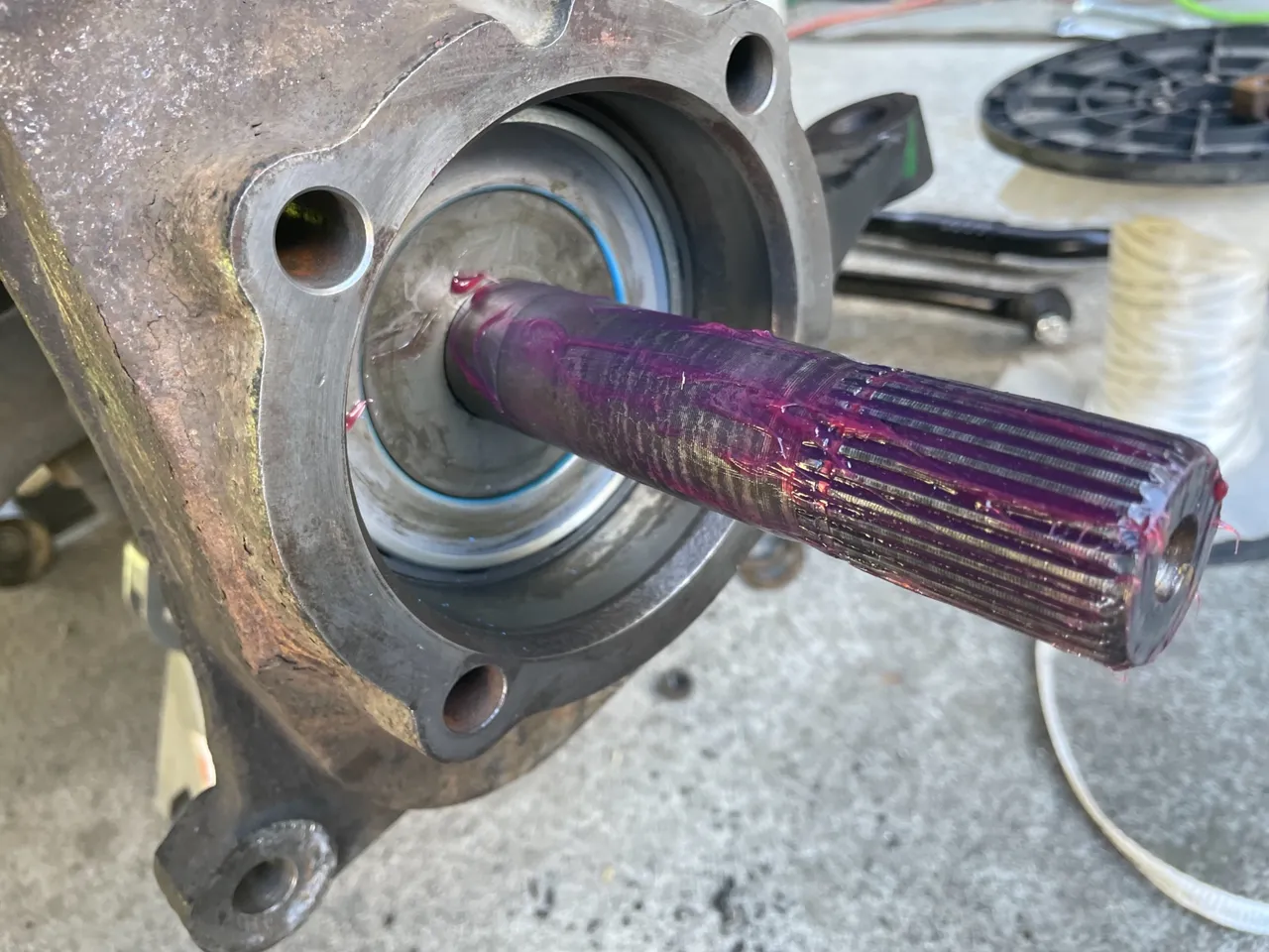
Then apply some axle grease to the axle shaft
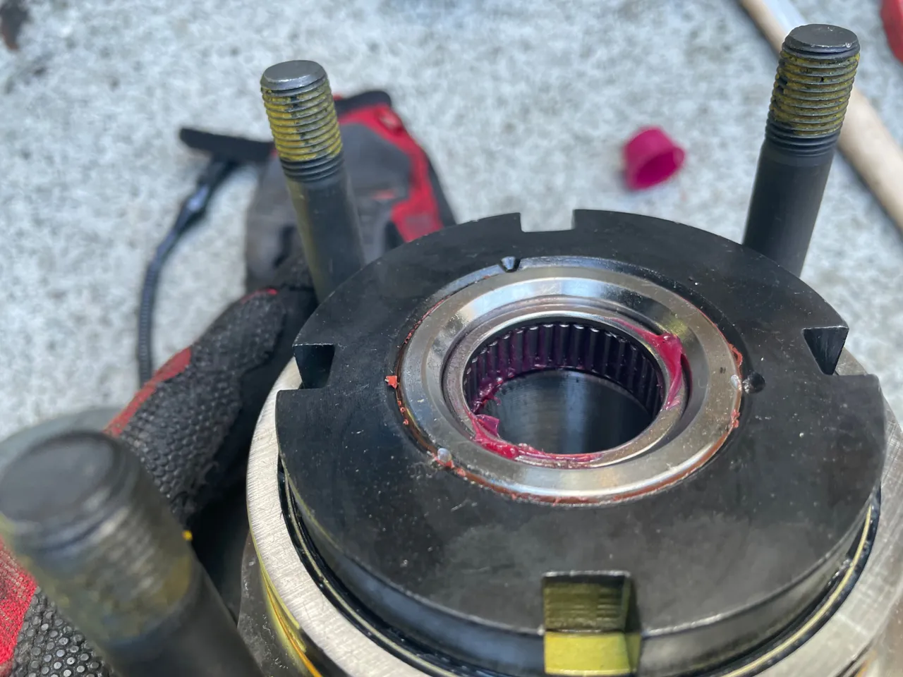
Put some more grease on the bearing inside the hub
Don’t forget the positioning of the dust shield that protects the brakes. You can use the other side for a reference if you forget. Position the hub so the ABS sensor is at the top and the cable routed under the flange on the dust shield
Push the hub all the way in and seat it into position. Then install the 4 nuts on the back side. Snug them all down then torque them to 130 foot pounds in a cross pattern.
Now it’s time to install the auto locking hub assembly. Place the thrust washers the same way they came out and install the snap ring.
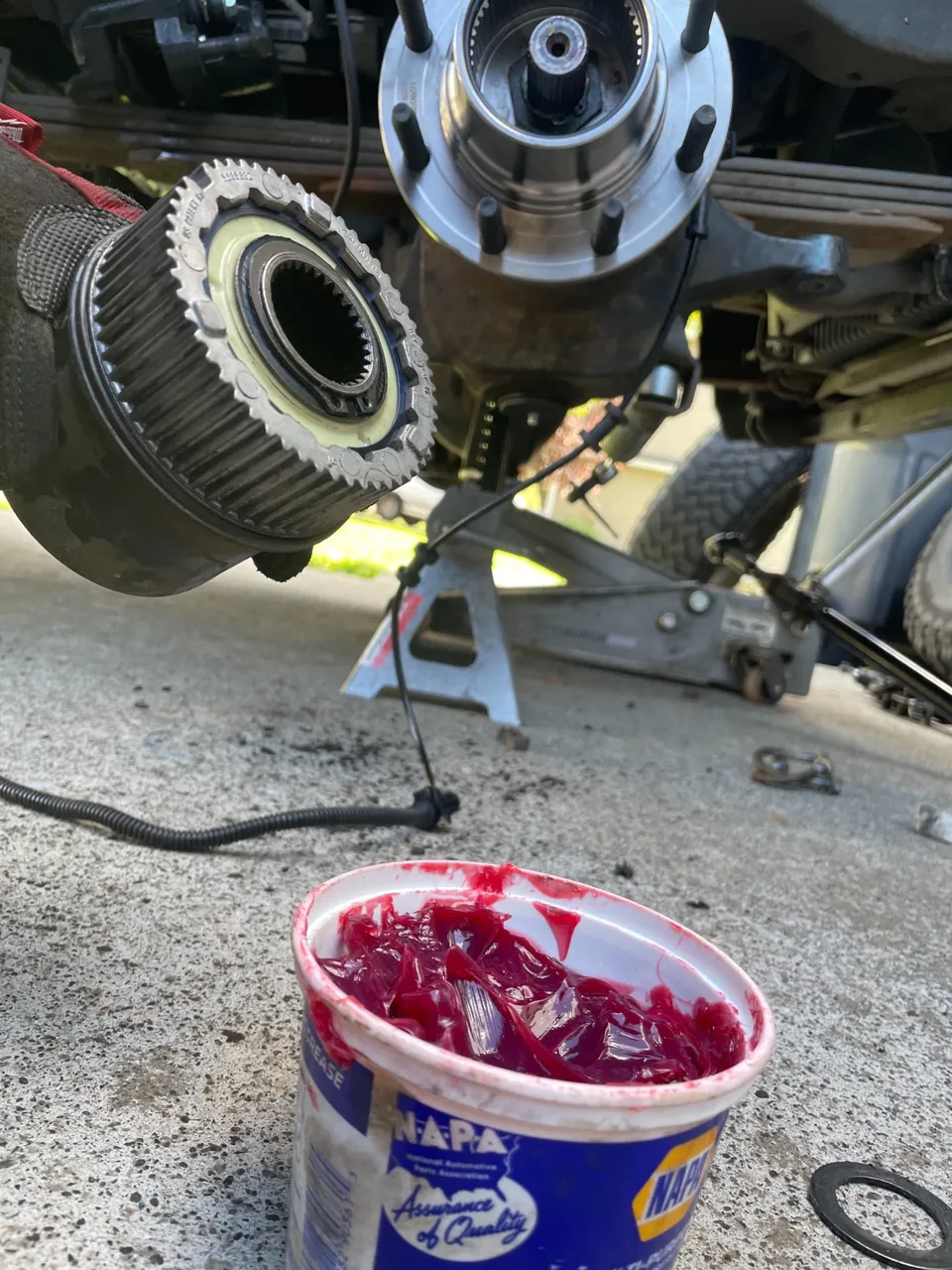
Then apply some more grease to the auto locking hub and insert it into the hub assembly
Once seated all the way in, install the locking ring on the outside
Then route the ABS speed sensor along the brake and vacuum line to the plug behind the fender well. Make sure to clip it into the provided clips. Install the 8mm bolt that holds the clip to the outer knuckle
Then install the brake caliper and bracket
It helps to rotate the bottom of the caliper toward the back of the vehicle and install the top first. Get the top bolt started then swing the caliper down and install the lower. Torque the bolts to 166 foot pounds.
Now all that is left to do it slap the tire on and torque the lug nuts down. Well I gotta do the other side too. Not to mention all the other stuff this Excursion’s front end needs… but this side is done
If you are wondering there are a few other things that were done while the hub & bearing assembly was off. You have to remove it in order to get to the axle seals, u-joints and ball joints. So stay tuned for Part 2 of the 2001 Ford Excursion Front End Rebuild when I change the dust seal and the outer vacuum seal.

Your Random
Dose of...