Here we are going to explain the tightening system of the cam, there are ten screws with head for Allen tool number 10. You torque from the center outwards, taking as a second step to the right, in the center as indicated in the drawing in the image.
Number 1 is pressed up and number 2 down then sequentially to the right and then to the left in the same way first up and then down, then back to the right and then to the left.
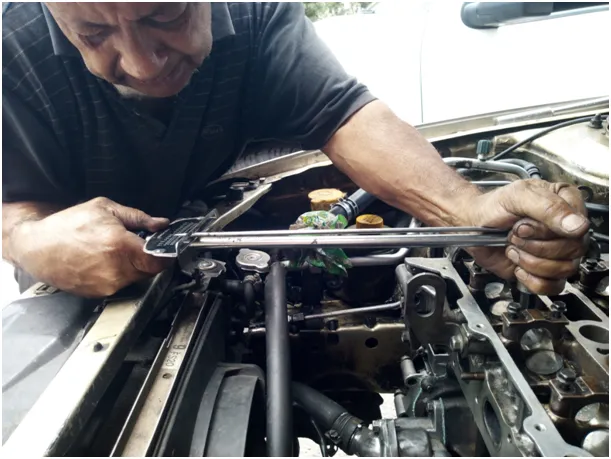
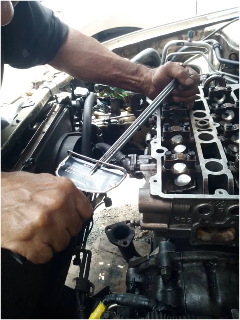
On the first adjustment take all the screws to 25 pounds, then repeat the operation taking the screws to 40, we repeat a third phase to 60 and the last adjustment can be taken to 70 pounds.
Here we see in the pictures how much it moved me to torque a screw.
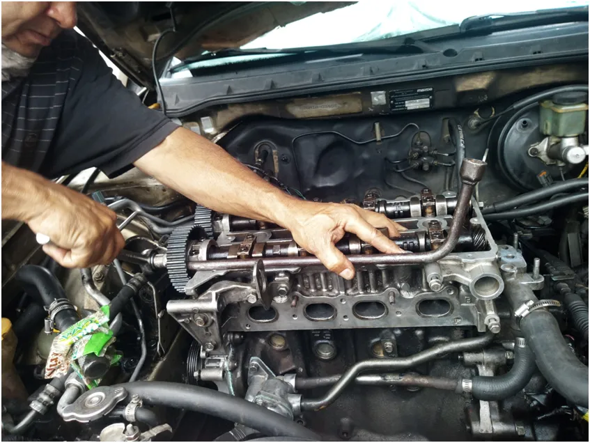
Now we mount the intake camshaft, it is the one that goes towards the side of the breeze stop, that the word says intake.
Where are the injectors that give gasoline inlet, has four bearings free adjustment in the chamber and the first bearing that carries a gland.
And its gear where the timing belt goes, these bearings are tightened very precisely, with 10 pounds of adjustment and a second phase to bring them to 18 pounds.
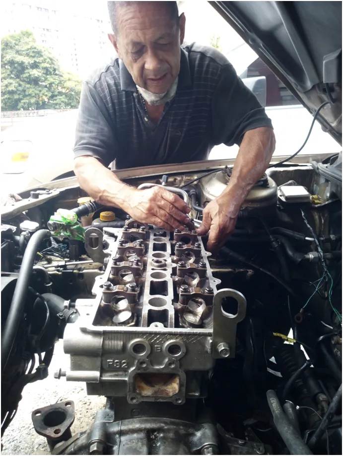
In the same way the exhaust camshaft is then mounted, as the word says, exhaust to where the exhaust manifold rests, also with its stopper, and its gearing where the timing belt goes.
For the tightening of this gear where the timing belt goes, we will use a lever or a tube, to rest it as shown in the photo, to prevent the gear from turning to the right when we tighten the screw.
We continue working
Wait for our next release
https://www.deepl.com/es/translator
All images are my property
You for reading my blog

ESPAÑOL
Muy buen día, tarde o noche, a mi querida comunidad de #Hive y #hivemotors. A sus integrantes y a los participantes. Por aquí estamos en esta oportunidad para hablar de la cámara
Mazda 626. Motor 2.0
Les vamos a hablar de la cámara
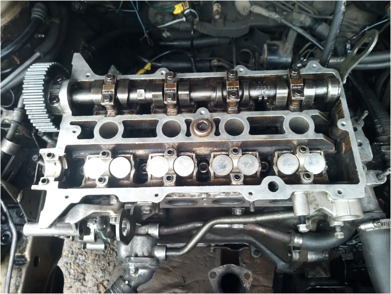
En esta oportunidad se está realizando el montaje de la cámara, el primer paso colocar la empacadura de la cámara, se le coloca grasa lubricante al bloque y luego se le coloca también grasa a la empacadura, para cuando se coloque la cámara haga su efecto. En la foto se observa la cámara solo con los taquetes y las conchas de sujeción, del árbol de levas.
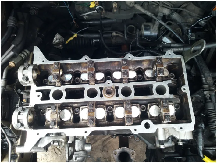
Y se monta sin los árbol de levas para estar con más espacio y comenzar torquear.
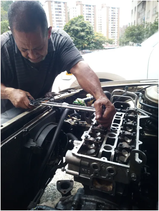
Aquí vamos a explicar el sistema se apriete de la cámara, son diez tornillos con cabeza para herramienta Allen número 10. Se torquea del centro hacia afuera, tomando como segundo paso hacia la derecha, en el centro como le indica en el dibujo en la imagen.
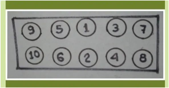
Se aprieta el número 1 arriba y el número 2 abajo luego a la derecha secuencialmente y luego a la izquierda de igual forma primero arriba y luego abajo, luego vuelve a la derecha y luego a la izquierda.
En el primer ajuste se llevan todos los tornillos a 25 libras, luego se repite la operación llevando los tornillos a 40, repetimos una tercera fase a 60 y la última de ajuste se puede llevar a 70 libras.
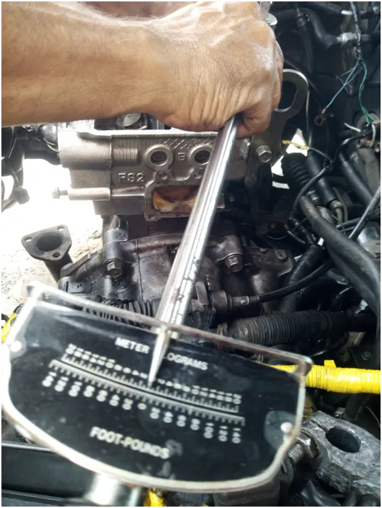
Aquí vemos en las fotos cuanto me movió para torquear un tornillo
Ahora montamos el árbol de levas de admisión, es el que va hacia el lado del para brisas, que la palabra lo dice admisión.
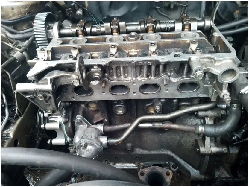
Por donde están los inyectores que dan entrada a la gasolina, tiene cuatro cojinetes libres de ajuste en la cámara y el primer cojinete que lleva una estopera.
Y su engranaje donde va la correa de los tiempos, estos cojinetes se aprietan con mucha precisión, con 10 libras de ajuste y una segunda fase para llevarlos a 18 libras.
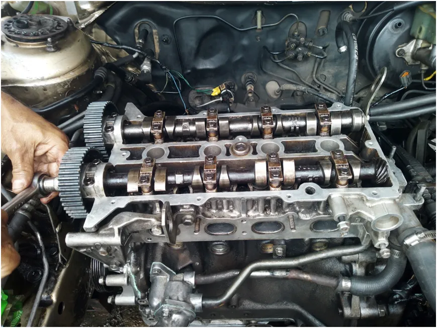
De esa misma forma se monta luego el árbol de levas de escape, como lo dice la palabra, escape hacia donde reposa el múltiple de escape de los gases, igualmente con su estopera, y su engranaje donde va la correa de los tiempos.
Para él apriete de este engranaje done va la correa de los tiempos, usaremos una palanca o un tubo, para reposarlo como aparece en la foto, para impedir que el engranaje gire hacia la derecha cuando apretamos el tornillo.
Seguimos trabajando
Esperen nuestra próxima publicación
Todas las imágenes son de mi propiedad
Gracias por leer mi blog