
Hello its a me again Drifter Programming! Today we get back to Logic Design to talk about FPGA's and all the basic knowledge you need to get started! I will start off talking about the Software (Quartus) we use and how we set up a project and run it on a FPGA. So, without further do, let's get started!
Intel (Altera) Quartus:
To do anything related with FPGA's we use a software from Altera (now Intel) that lets us:
- write code (VHDL, Verilog or even Block/Diagram-based)
- simulate the circuits (Modelsim that we used in my VHDL series)
- setup the pins and assigments (depending on the FPGA)
- upload the code to the FPGA to run it (using an USB Blaster or Ethernet cable mostly)
Software download:
You have to register at this page and download the version that suits you.
For example if you have a Cyclone V you have to go to this page:
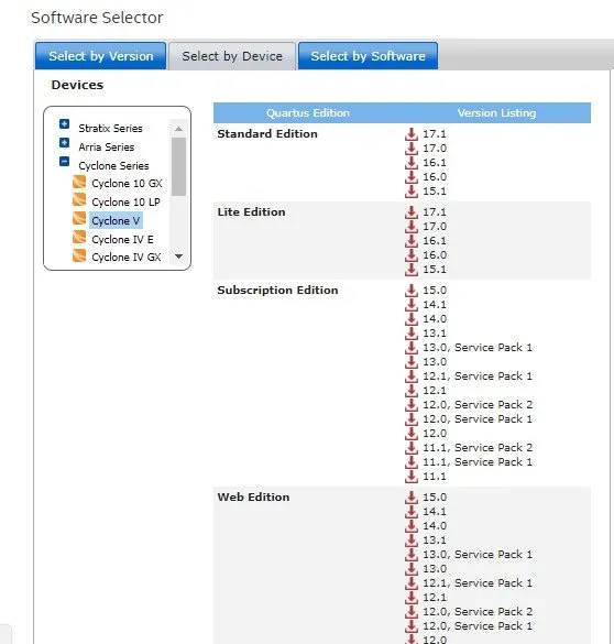
And there you can select any edition you want, but I recommend the Web Edition cause they tend to be smaller. Older FPGA's will need an older version, cause they will not by compatible with newer versions.
Setting up a Project:
I have an older FPGA (Cyclone I) and so I use an much older version (9.1sp2) of the software, but the Interface actually only changed in Style and not in Features and so you should not have any problem following along.
When opening the Software you will be in a Page that looks like this:

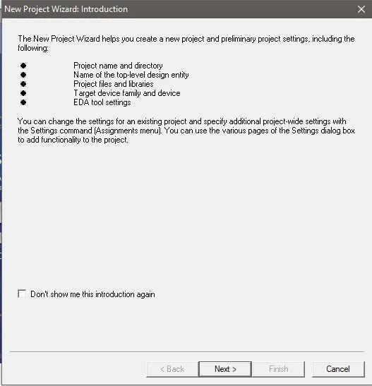
There you can click at "Create a new Project" and a new popup window will come out, where you will specify the project location, name, libraries (predefined code) you want to include, the FPGA you use, a Simulation software and so on...
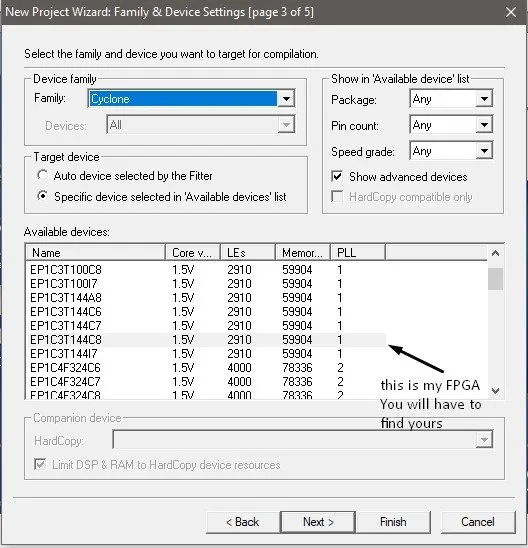
So, to create a Project for my FPGA the Cyclone ep1c3t144c8 I do the following:


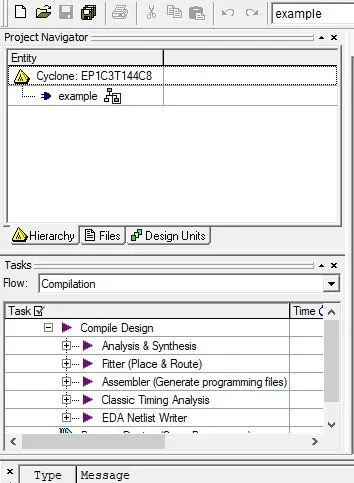
Now on the left you should see the following:
Writing the Code using VHDL:
We have to create a new VHDL file...


As you can see there are many ways of writing a Circuit, but let's stick to VHDL for now, cause I also have the Series where I cover everything you need to write a simple to advanced Circuit!
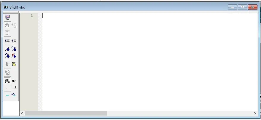
Let's write a simple AND Gate...Puff!

Don't forget to put the top-level entity name you put when creating the project!

Now it should be inside of the "Files" tab.

We have to set it as the Top-Level Entity, cause else we get an Error!

Let's now finally compile it!


And this is actually all there is to write code (well...mostly)!
The problem is the pin's are mostly in "inverse" logic inside of an FPGA. So, when giving an input of '1' the input will actually be '0' and vise versa. The same applies to the Output! Let's change it quickly...

This will get us confused when we use a PLL clock for example, cause instead of checking for an rising_edge we would have to check for an falling_edge, cause the values of the clock will also be inverted.
You might now want to kwow why this happens. Well, it's simple. When giving input we actually set the signal to '0' cause the input works like a switch and so "cuts off" the signal. So, all the pins give '1' by default and to get '0' we will have to "turn a switch". That's why everything will be inverted. If you get used to it it actually is not so difficult!
Pin Assigment (depends on the FPGA):
All the FPGA's will have different pins and these pins are given by the manufacturer. The pin assignment pdf for my FPGA is in chinese (!), but the keywords for the switches, leds and so own (cause I have a development board) are all with english letters and so I could create some simple circuits using it.
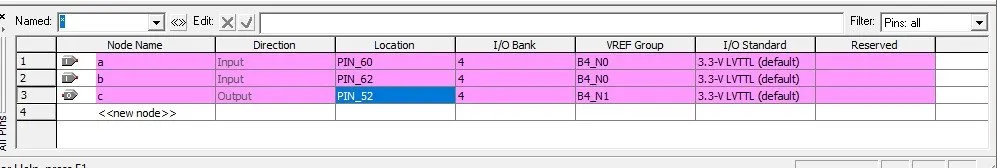
To assign the pins you go to the Pin Planner...


After compiling once you should have the Inputs and Outputs already defined as names, but not in specific pin locations.
From my pin assignment sheet I know that PIN_60 and PIN_62 are K-Switches (buttons) and PIN_52 is an LED and so I put those....
And this is actually it! Now we only have to upload it to the FPGA and run it!
Uploading and Running the Code on the FPGA:
Depending on the FPGA you might have to use a USB Blaster with JTAG (like mine), Ethernet Cable or other methods. The way you upload should be mentioned by the manufacturer.
After compliling you open "Program Device" and setup the Hardware....

You should have a file that can be uploaded to your specified device.
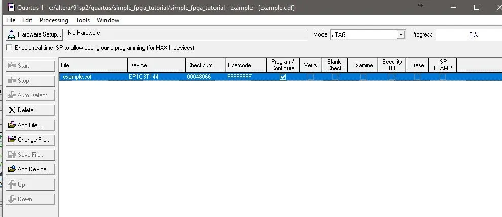
If the Start button is greyed out, then you will have to select the Hardware from the "Hardware Setup" menu. Because, of so many updates in Windows I can't run this FPGA anymore, cause there are no drivers for the USB Blaster and so the FPGA is not being recognized.

This is something that you should consider before buying something older!
But, I assure you that if you click the "Start" button and it successfully uploads to the FPGA then you will be done and everything should work just fine...
For example running this Code we suspect to see the following behavior:
- When none or only one of the two buttons is pressed the led should be off
- When both buttons are pressed the led should be on
And I think that we are done now!
I hope that this post helped you get started with FPGA's! As you can see it actually is not quite difficult, but you just have to follow specific steps. I may upload something more advanced in the future, but for now this is all I can do, because of Driver limitations mostly!
Thanks for spending your time reading this post!
Bye!