Custom Thumbnail that contains: 
Introduction
Hello it's a me again Drifter Programming! Today we continue with Electromagnetism to get into how Electromagnetic waves interact with matter, which includes how they affect and how they are affected by matter. So, without further do, let's get straight into it!
EM wave propagation
Let's start out with the basics of EM wave propagation. As already told in my "Introduction" article, electromagnetic waves can travel through a vacuum of space, unlike mechanical waves that always require the presence of a material medium. This means that EM waves are a way of tranporting energy from one place to another through a material medium, but also in the absence of such a medium (vacuum). The "best" EM wave example is of course light or better said "light waves", as light has two natures (particle and wave). When in a vaccum such waves travel at the speed of light c. When propagating through a material medium their net speed becomes less than c, cause their wave energy is being absorbed and reemitted by the atoms of that material. More specifically the absorption of energy by the atoms of the material causes these atoms to undergo some vibrations. After a short period of vibrational motion, the vibrating electrons of the atom then create a new electromagnetic wave, that of course has the same frequency as the first electromagnetic wave. Even though this vibration takes up very short time, it still delays the motion of the wave through the medium. This exact thing happens for each atom of the material that the EM wave has to pass through. There of course is a small region of space between each atom (interatomic space), where the EM wave travels at the speed of light, but either way the net speed of the EM wave comes out to be less than c, even if it is by a small amount. The "speed loss" of the EM wave depends on the so called optical density of the medium, which means that different materials have a different amount of delay in the absorption and reemission process. The propagation speed also depends on the actual atomic density of the material or how close the atoms are to each other. Altogether both of these factors depend on the material we are talking about, and so in the end the speed of an EM wave that passes through a material, depends upon the material.
Angular distribution, polarization and scattering
Angular distribution
The speed of an Electromagnetic wave is not the only thing that changes when travelling through a material medium or interacting with matter in general. Using the propagation direction as it is described by the Poynting vector that we covered last time, we can start talking about the actual change in direction of an EM wave. For an electric dipole radiator whose EM wave propagates along the x-axis, the electric field points along the z-axis, whilst the magnetic field is in the x-y plane, circulating around the z axis. The angular distribution of this radiated field is of the form:

where:
- S is the Poynting vector
- θ is the angle with respect to the z-axis
- r the radius of the magnetic field's circular motion
Polarization
This shows us that the electromagnetic wave is polarized wit the electric field vector E oriented parallel to the z-axis. Such a wave can being reflected by the current induced in wires of "good" conductors when this grid of parallel wires is inserted between the source and detector, having the wires parallel to the electric field vector. When having these parallel wires perpendicular to the electric field, then the wave is being transmitted "normally". Such a grid serves as so called polarization analyzer, which means that it can be used to analyze the polarization of light, analogous to polaroid materials.
Scattering
Electromagnetic waves can be scattered by free and bound-to-atoms charges. When interacting with such waves, they start oscillating along the direction of the electric field vector E. After this oscillation (or vibration as we called it before) is done, these charges reradiate like small electric dipoles. The coherent oscillations of free electrons in metal or plasma lead to the reflection of the incident wave at frequencies below the plasma oscillation frequency. Above that frequency the electromagnetic wave/radiation is being transmitted and scattered by reradiation, by the charges that are oscillating in the incident electromagnetic field.
The scattering of sunlight by the atmosphere is a nice example of the scattering of EM waves. The bound electrons in atoms have a resonance in the ultraviolet region. The eye is sensitive to light that at spans frequencies just below that resonance frequency. Using that we can proof that the power radiated by these reradiating, oscillating and bound electrons is:

where:
- q is the charge of the electrons
- m the mass of the electrons
- E0 the incident electric field magnitude
- ω the incident frequency
- ω0 the resonacne frequency of the electrons
- θ the angle with respect to the electric field of the incident wave
The reradiated power peaks perpendicular to the incident frequency, which is why much more red then blue light is being scattered by the atmosphere. This explains why the sky looks blue. The setting sun looks red, because the blue component is being scattered away following a long path. The atmosphere becomes opaque at resonances near the UV region, something that helps reduce the risk of skin cancer, whilst at high frequencies above the UV the scattering becomes smaller and smaller.
All that we said till now shows us how EM waves are affected in general, let's now get more in-depth to analyze the specific cases of Conductors, Plasma and Dielectrics.
Skin effects on Conductors
All materials contain ions and electrons that of course experience the Lorentz force when exposed to electromagnetic fields, which include waves. In conductors, electrons move around freely, although they suffer from frequent collisions with ions (lattice). The motion of these free (unbound) electrons in an electric field can be described by the mathematical expression (as equal forces):

where:
- m is the mass of the electron
- dv/dt = a the acceleration (yes the left part is F = ma aka Newton's second law)
- e is the charge of an electron
- E the electric field vector
- u the collision frequency
- v the velocity of the electrons
The magnetic force term of the Lorentz Force (vxB) is being ignored...
Assuming that the electric field is varying following the equation:

the velocity of the electrons is given by:

Maxwell's equations require the density of current that is of course easily described by the so called "drifting" velocity of the electrons. Multiplying the electron velocity with the electron charge density "-ne" (n is the electron density) we get the current density:

That way Ampere's law (the fourth Maxwell equation) becomes:
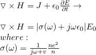
σ(ω) is the so called ac conductivity.
Through-out this series we talked about the current conductivity σ and displacement current conductivity jωεo. this "new" conductivity becomes comparable when:

In practical problems the frequency ω is much smaller then the collision frequency u. Also, the displacement current becomes negligible compared to the conduction current. Therefore the "simple" dc conductivity (that supposes conductive current only) is:

The basic Maxwell equations that describe the electromagnetic fields in conductors are:

Elliminating the magnetic field and ignoring the charge accumulation we obtain:

These equations are called diffusion equations. Electromagnetic field don't propagate that freely in conductors, but encounter a strong resistance. After a steady state is being established, when an oscillating field is being applied in a conductor, we can describe the electric field in the conductor by:

Let's assume that we work in one-dimension. An external field He^jωt is applied parallel to the conductor surface (z = 0). This turns the previous equation into:

Solving this we get:

δ is the skin depth, which measures how deep the electric field, current and magnetic field can penetrate into a conductor. Being proportional to sqrt(ωσ) we see that the penetration becomes more difficult at higher frequencies and in better conductors. These skin effects modify the resistance and internal inductance of a wire from those dc fields. The resistance and internal inductance per unit length of wire, with radius a and conductive σ are:

This shows us that the resistance is increasing becauses the effective cross section area for current flow decreases. The internal inductance on the other hand decrease, because the magnetic energy stored in the wire becomes smaller.
Diffusion
Having a skin effect, the dc electric field cannot instantaneously penetrate into the conductor, but gradually diffuses into the conductor following the diffusion equation:

Considering a characteristic dimension a for the conductor, an order of magnitude estimate for the field penetration time (τ) across this distance a is:

Let's suppose that the dc external field is applied at t = 0, again one-dimensional the diffusion equation becomes:

At first (initially) Ez(x) = 0, t= 0.
We define a so called boundary condition which is:

This can be solved with the method of variable separation if we assume:

which separates the equation into:

Appyling the boundary conditions we get the following solution;

τn is the penetration time of n-th spatial harmonic mode.
The coefficient An can be determined by the initial condition:

After some calculations we get:

The final solution for Ez(x, t) comes out:

For conductor rods of radius 'a' we would get:

With "ka" being the n-th root of Jo(ka) = 0.
For this case the penetration time (τ) comes out:

EM waves and Plasma
Let's now get into another material / type of matter...
Plasma is an ionized gas that consists (only) of free ions and electrons. Containing both positively charged ions and negatively charged electrons, a charge neutrality can only be accomplished when the positive (of ions) and negative (of electrons) charge densities are equal to each other. Waves in plasma are quite diversified when the plasma is inside of an magnetic field. Plasma production requires a significant amount of energy. For magneto/ionospheric plasma, the energy source is solar wind. Laboratory plasma can only be maintained when sufficient energy is continously fed. A hot, high density plasma tends to be electromagnetically unstable and so it releases energy to approach thermal equilibrium with the environment. The positive aspect of this unstability is that plasma can be a source of high frequency, high power micro waves.
Let's now get into how the plasma modifies the wave equation in vacuum...
As we already saw previously the ac conductivity is given by:

For gaseous plasma, the collision frequency v is negligible, cause gas has a much power particle density then a solid. From that we get that the ac conductivity of plasma is approximately:

Ampere's law (fourth Maxwell equation) therefore becomes:

ωp^2 is the square of the plasma frequency.
From all this we see that the effective permittivity of a plasma is given by:

which is much smaller then ε0 (permittivity of a vacuum).
That way the dispersion relation of electromagnetic waves in plasma is:

The constant k is being called the phase constant (or wavenumber).
For ω < ωp this constant becomes purely imaginary:

This shows us that the waves become strongly damped (for ω < ωp) and cannot propagate in a plasma of such a high frequency.
The characteristic impedance of plasma is:

The spatial exponential damping length at the air (or vacuum) plasma boundary is given by:

This is a quantity similar to the skin depth of conductors, which here now shows us the collisionless skin depth of the plasma. This quantity gives us a masure of how deep a low frequency electromagnetic field can penetrate into a plasma.
AC Permittivity of Dielectrics
The permittivity of dielectrics for dc fields is given by:

For ac fields this turns into:

where:
- ωp is the effecitve plasma frequency
- ω0 the frequency of the bound harmonic motion
- ω the indicent field frequency
In absence of external electromagnetic fields, an electron bound to an atom or molecules undergoes an harmonic motion of the form:

When an oscillating electric field E e^jωt is applied this changes into:

Differentiating once we then find the steady oscillatory solution:

Using this velocity, the electron current density is therefore:

Now that we calculated this density we can change the 4th law again as following:

The previous ac permittivity that I gave was the effective ac permittivity. The special case ω0 = 0 (perpendicular magnetic and electric wave) gives us:

where ωc = eB/m is the electron cyclotron frequency.
The cyclotron frequency appereance can be explained by the cyclotron motion of the electrons, which is equivalent to those undergoing bound harmonic motion in dielectirc. Some crystals have anisotropic dielectric properties, because the electron polarizability is not uniform (anisotropic) and so the polarizability along a certain axis can be large than in other direction, causing double refraction phenomena.
REFERENCES:
- https://www.physicsclassroom.com/mmedia/waves/em.cfm
- http://www.pas.rochester.edu/~cline/P114/Chapter16.pdf
- http://physics.usask.ca/~hirose/EP464/ch10-09.pdf
Mathematical equations that I had in this post where drawn using quicklatex!
Previous articles of the Electromagnetism series
Here we only have the previous two "chapters" and the current one!
Mutual and Self Induction:
Mutual Inductance -> Mutual Inductance, applications
Self Induction -> Self Induction, Lenz's law, Inductance of a Coil
Magnetic Energy Density -> Energy stored in a magnetic field (or inductor), Magnetic energy density, Coaxial Cable Inductance Example
R-L circuits -> R-L circuit energizing, de-energizing, Characteristic time constant
L-C circuits -> L-C circuit, oscillations, energy cases, applications
R-L-C circuits -> R-L-C circuit, oscillation, applications
Mutual and Self Induction exercises -> examples all around Mutual and Self Induction
Alternating current:
Getting into Alternating current -> Phasor diagrams, Alternating current, Average (RMS) current and voltage, Differences, Advantages/Disadvantages
Electric Reactance in AC circuits -> Resistors, Inductor and Capacitor Reactance in AC circuits
Series R-L-C circuits Impedance -> Series R-L-C circuits, Phasor Diagrams, Impedance
Power in AC circuits -> DC Resistive circuit, Power in AC circuits (resistive, reactive), Power Factor
Resonance in Series R-L-C circuits -> Series R-L-C circuit, Series Resonance
Resonance in Parallel R-L-C circuits -> Parallel R-L-C circuit, Parallel Resonance
AC Transformers -> How they work, Configurations, Types, Voltage and Current Transformer
Alternating current exercises -> examples all around Alternating current
Electromagnetic waves:
Electromagnetic Wave Introduction -> Electromagnetic waves, velocity, wave equation
Sine waves and EM wave energy -> Sine waves, energy density, EM wave power, Poynting vector, Radiation pressure / Energy momentum
Final words | Next time
And this is actually it for today's post and I hope that you enjoyed it! Next time we will continue on to talk about Standing Electromagnetic waves.


Keep on drifting!